A dynamization is configured in the dynamics editor. Click on the button ![]() in the toolbar to open the dynamics editor.
in the toolbar to open the dynamics editor.
Basic procedure
-
Drag the objects for which a dynamization is required into the panel, prior to creating the dynamization.
-
Create a new dynamization.
-
Select a signal that controls the dynamization.
-
Define the states to be executed during the dynamization. To do this, it is necessary to activate configuration mode.
-
Configure the objects used with the desired properties for each state and transitions between the states. When you have finished editing, turn configuration mode off again.
You will find a more detailed description in the following description of the dynamics editor and an example.
Note |
|
|---|---|
|
The object states can only be changed if configuration mode is active. |
|
Operation in the dynamics editor
Dynamizations are configured for a specific panel. If several panels are already configured, you can select a panel in the drop-down menu (1).
Click on the button to create a new ![]() dynamization. Existing dynamizations can be selected from the drop-down menu (2).
A selected dynamization can be removed by clicking on the
dynamization. Existing dynamizations can be selected from the drop-down menu (2).
A selected dynamization can be removed by clicking on the ![]() button.
button.

Name
Enter a clear name here.
Channel
Select the ibaPDA signal that is to control the movement from the Channel drop-down menu.
Interpolation
The transition between two states can be defined here. Available for selection are:
-
Steps: there will be no interpolation between states here. The associated state is first displayed once the next signal value is reached.
-
Linear: the change of the property between two states will be interpolated linearly. Please note that not every property, such as font types, can be changed linearly.
-
Ease in: Transition with a slow start accelerated towards the end
-
Ease out: Transition with a quick start that gets slower at the end
-
Ease in and out: Transition starts and ends slowly and accelerates in between
Interpolation curves of the different transitions:

Enabled
Here you can enable and disable the dynamization. Thus it is possible to preconfigure a dynamization and to apply it later.
Variables/affected tools
As soon as configuration mode is activated and you make changes to an object in the panel, the name of this object appears in the affected tools field. The modified property is also automatically added as a variable in the Variables field. Properties and objects can also be deleted directly in these fields.


Use the select button ![]() to select all objects. By clicking on the name, a single object can be selected,
too.
to select all objects. By clicking on the name, a single object can be selected,
too.
States

The states “Default,” Begin" and “End” are available by default. The default state describes the state of the objects when switching from display mode to design mode. The begin and end state describes the state of the objects at the beginning and end of the dynamization.
The states can only be edited or new ones added if configuration mode is activated via the <Configuration mode> button. If configuration mode is active, the button turns green. When the editing is finished, configuration mode can be deactivated by clicking the button again and the color of the button changes back to gray.
Additional states can be added (![]() ) and removed (
) and removed (![]() ) using the control elements. A signal value can be assigned to every state that will
be entered numerically in the Value column. In the Percentage column, the percentage of the signal value from the end value is automatically entered.
) using the control elements. A signal value can be assigned to every state that will
be entered numerically in the Value column. In the Percentage column, the percentage of the signal value from the end value is automatically entered.
In case a state is marked, the related properties can be defined. For this purpose, there are 2 methods available:
-
Mark the object in the panel for this task and change here the properties of the panel, such as the placement and/or the color. The object and the changed properties will be automatically applied in the dynamics editor.
-
Open the “Edit Properties” dialog by clicking on the button
 . In this dialog, all objects that belong to this dynamization are displayed with
the related properties.
. In this dialog, all objects that belong to this dynamization are displayed with
the related properties.

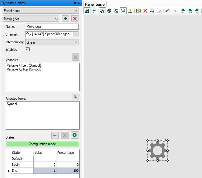
Procedure by means of the example „Move gear"
The aim of the example is the linear movement of a graphics element (symbol) from position 1, if the signal value is 0, to position 2 at the maximum signal value 800.
-
Drag the symbol object onto the panel.
-
Create a new dynamization and enter a name (Move gear).
-
Select the signal that is to control the movement.
-
Select the interpolation “Linear”.
-
Activate configuration mode via the <Configuration mode> button.
-
Define all desired states and the related signal values. The signal value 0 is assigned to the initial state, the signal value 800 to the end state (this corresponds to the real signal range and should be known).
-
Mark the “Begin” state and drag the symbol to the start position while keeping the mouse key pressed.
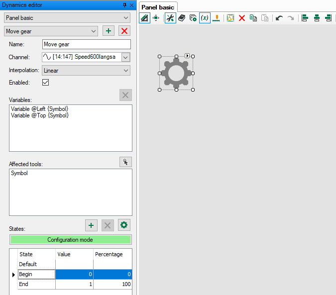
The object will be displayed in the Affected tools field, and the changed properties in the Variables field.
-
Mark the “End” state and drag the symbol to the end position while keeping the mouse key pressed.
-
Both positions can be controlled or corrected, if the respective state is marked.
-
Exit configuration mode by clicking the <Configuration mode> button.
-
Click <OK> to close the dynamics editor.
-
If you switch to display mode, the symbol will move between both positions according to the signal value.

