-
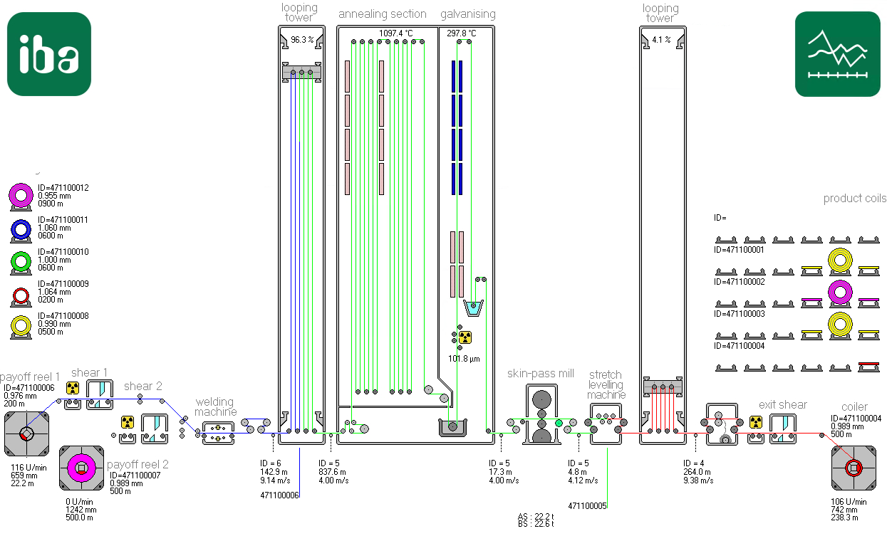
Identify the line type and the associated line properties (e.g. maximum speeds, operating modes and functions, such as reversing mode, etc.). A line diagram (Visio or AutoCAD drawing, HMI overview diagram or similar) should always be available. Example: HMI overview of QDR simulator
-
Clarify which data is relevant for quality in your application and therefore needs to be stored. It may be useful to involve the quality department at this stage.
-
Clarify the data sources and thus also the data interfaces that are required for ibaQDR to acquire the measurement signals (including any options requiring a license).
-
Identify the line sections with different speeds than one another, for example, the number and positions of the installed bridle rolls for speed measurement in a strip processing line.
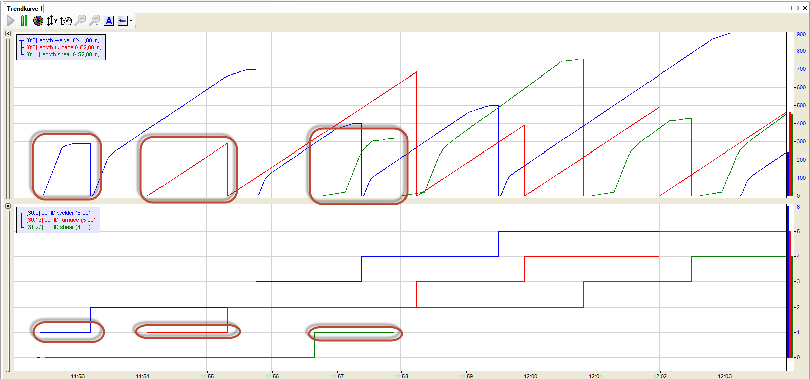
At the top, the figure shows a simplified view of three different speed ranges using the example of length measurement in a strip processing line: Welder in the entry section (blue) with acceleration and deceleration, furnace (red) with constant speed and shear in the exit section (green) with acceleration and deceleration. The graph below shows the tracking IDs.
-
Identify locations in the line where a change of length (elongation) of the product occurs, e.g. roll stands, stretcher leveler, etc.
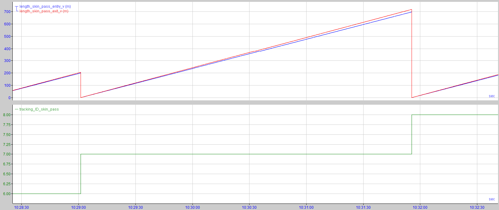
At the top, the figure shows an example of measured length values for the entry side (blue) and exit side (red) on a skin pass mill (approx. 3% skin pass level). The graph below shows the tracking ID.
-
Identify which sensors or which signals are available for precise material tracking, e.g. hole detectors for weld seam tracking.
-
Define the text telegrams and text signals that ibaQDR receives to write the product-specific information to the data file and name the finished product files.
-
Specify the measuring locations along the line (type, number, position).
-
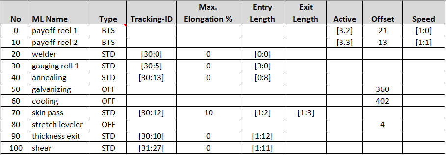
Specify the signals that ibaQDR requires from the material tracking system for each section of the line (measured length or speed values, tracking ID, offsets, etc.). This step is best carried out using a spreadsheet, e.g. MS Excel.
-
Specify the measurement signals to be measured during operation and assign them to the relevant measuring location.
-
Establish the connections between the ibaQDR system and the data sources (PLC, level 2).
-
Configure the input signals in the I/O manager (signals from material tracking system, process signals, text signals).
-
Configure the data store.
-
Check the DAT files generated by ibaQDR.


