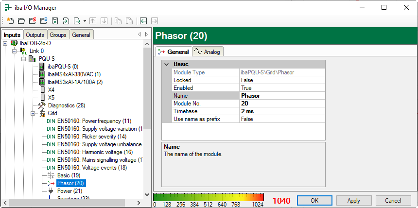
General tab
Basic settings
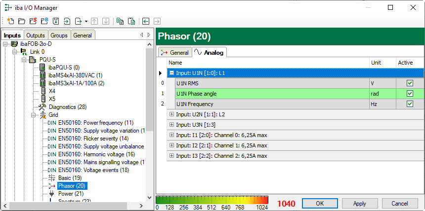
Analog tab
The Phasor submodule acquires the following characteristic values for each input:
-
RMS value, phase angle, frequency, measurement interval 200 ms
In the signal display, the signals are grouped by input. Click the <+> sign before the group name to show the signals of a group.
Name
The names are set by default but can be edited. For unambiguous identification, they
contain the input channel and the characteristic value. You can additionally assign
two comments when clicking the ![]() symbol in the Name field.
symbol in the Name field.
Unit
Display of the unit.
Active
Here you can enable or disable the signal.
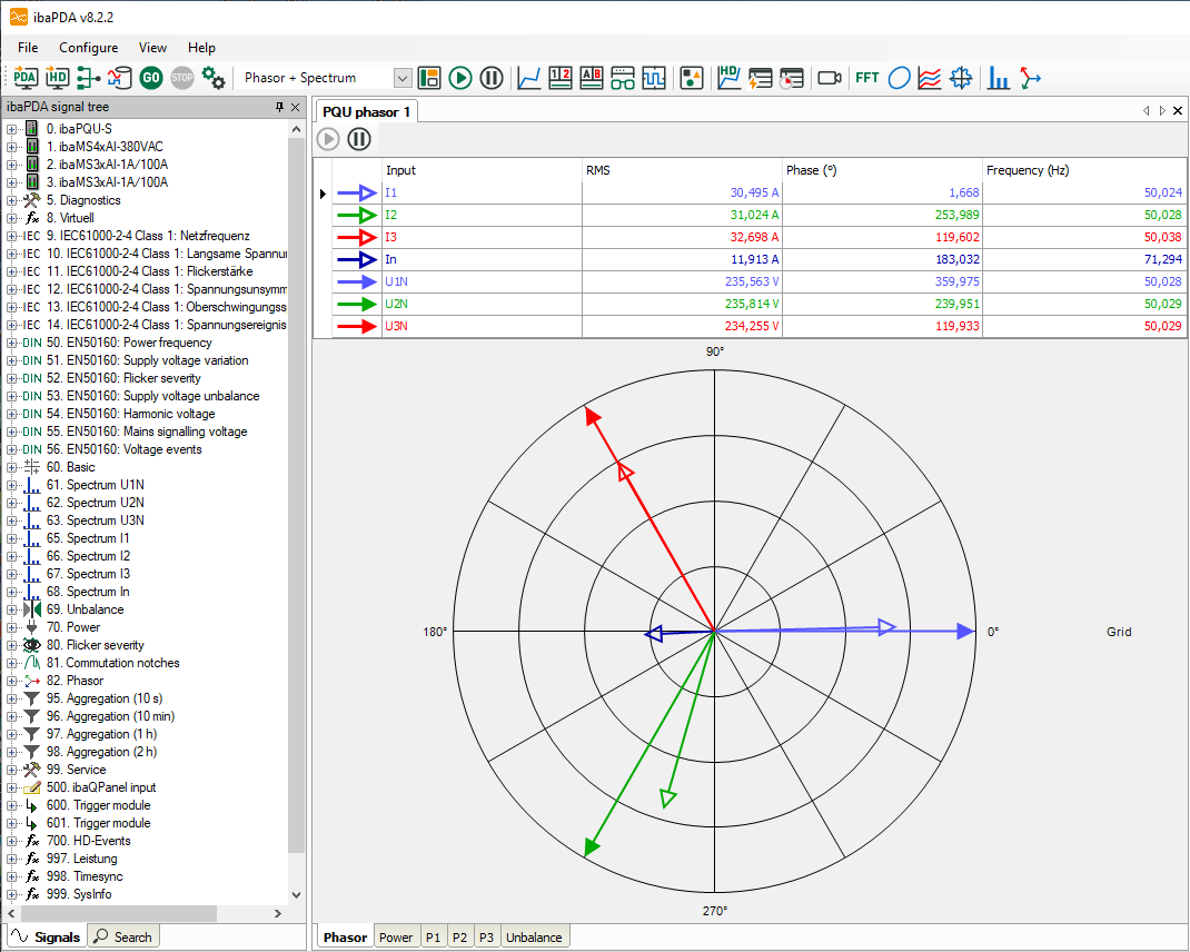
Display in the phasor diagram (phasor view)
The voltage and current characteristics of the 3 phases can be visualized in a phasor diagram.
You can open the display of a pointer diagram by clicking on the button ![]() in the toolbar of ibaPDA.
in the toolbar of ibaPDA.
Hold the mouse button down and drag the Phasor or Basic module from the signal tree on the left onto the display.
-
Filled arrowheads: RMS value of voltage in the corresponding phase angle
-
Empty arrowheads: RMS value of current in the corresponding phase angle
Note |
|
|---|---|
|
In TN systems (TN-C, TN-S, TN-C-S), measurements are made against the neutral point (neutral conductor N). Since there is no connection to the neutral point in IT systems, a different representation may occur in IT systems. |
|


