The Aggregation submodule is a freely configurable module in which the measurement interval and the characteristic values can be selected individually. The submodule name is assigned automatically by ibaPDA and is in accordance with the set measurement interval. The default setting is 10 min. If the measurement interval is modified, the module name will change accordingly.
Note |
|
|---|---|
|
Details on the aggregation method:
|
|
General tab

Basic settings
Module layout
No. analog signals
Enter the number of desired signals here. The number determines the length of the signal table in the Analog tab.
Configuration
Update time
Select the measurement interval here.
-
The following default intervals are available: 200 ms, 3 s, 10 s, 10 min or 2 h
If you choose a default interval, the Unit and Amount fields will show the matching values and cannot be edited.
-
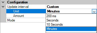
Custom
The “Custom” selection allows you to freely define the measurement interval using the Unit and Amount fields.
Select the unit:
Enter the amount (number of units) as an integer value into the field.
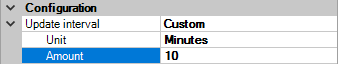
The defined amount and the unit determine the measurement interval and automatically the name of the module.


Mode
-
Custom: Select “Custom” to configure the analog signals in the Analog tab to your preferences.
-
Auto: Select “Auto” to show the additional line “Signals based on”. Click on the arrow to open a drop-down menu that contains all submodules that have already been created:
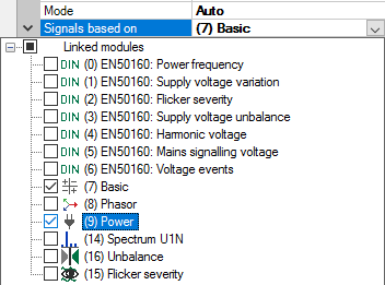
The submodules can be selected individually. The characteristic values configured in them serve as the basis for the new measurement, however with the measurement interval defined here.

Analog tab
The display in the Analog tab depends on the settings in the General tab.
In the following example, we selected “Auto” mode and the submodules Basic and Power. The characteristic values defined in the submodules are listed in the Analog tab.

Name
The names are already preset. For unambiguous identification, they contain the input
channel and the characteristic value. You can additionally assign two comments when
clicking the ![]() symbol in the Name field.
symbol in the Name field.
Function, order, unit
Displays the properties
Active
Here you can enable or disable the signal.
In the following example, the “Custom” mode was selected. The Analog tab shows no entries at first.

Name
You can select any name. You can additionally assign two comments when clicking the ![]() symbol in the Name field.
symbol in the Name field.
Function
Select the characteristic value to be calculated from the drop-down menu: Phase, Peak value, …

The calculations applicable to the selected input signal are shown in green.
Order
If one of the harmonics or interharmonics is selected under Function, you can enter the order 1-50 here.
Input
Select the input to be measured.

The input signals that match the selected function are displayed in green.
Unit
The unit is inserted automatically.
Active
Here you can enable or disable the signal.
Special considerations for grids with user-defined nominal frequencies
In addition to grids with 50 Hz and 60 Hz nominal frequency, ibaPQU-S also allows taking measurements in grids with a user-defined frequency. If a user-defined power frequency is set (in the PQU-S module), this will influence the length of the 200 ms measurement interval and the naming in the Aggregation submodule.
With a 200 ms interval, exactly 10 periods are measured in 50 Hz grids and 12 periods in 60 Hz grids, equivalent to exactly 200 ms.
With user-defined power frequencies, 10 or 12 periods are measured accordingly: 10 periods for power frequencies ≥ 10 Hz and < 51 Hz, and 12 periods for power frequencies ≥ 51 Hz and < 80 Hz.
For the set power frequency, the interval time is then calculated for 10 or 12 periods.
Example:
If 16.7 Hz power frequency is set, 10 periods are measured. The measurement interval is calculated for 10 periods and is 598.8 ms.
The interval of 598.8 ms is then also displayed in the drop-down menu and replaces the 200 ms interval.

The calculated measurement interval also determines the module name.
