General tab
Basic settings
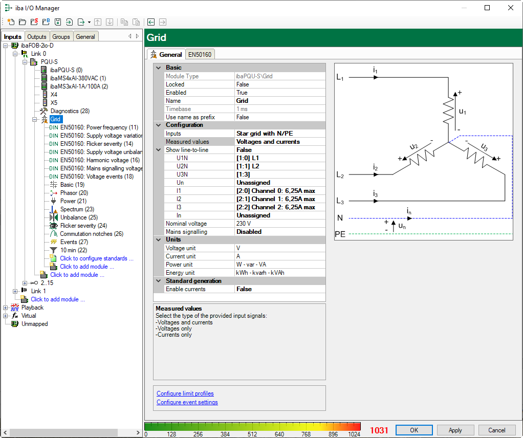
See PQU-S – General tab.
Configuration
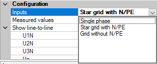
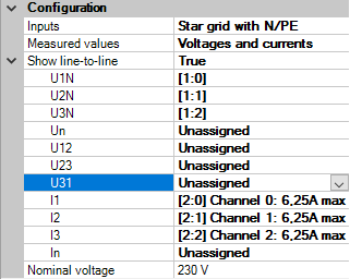
Inputs
Select the grid type.
Depending on the grid type, the input measurement signals required for the grid type are displayed in the rows below.
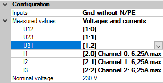
Assign the corresponding input signals to the measurement values.Example: Grid without N/PE
Required signals: U12, U23, U31, I1, I2, I3
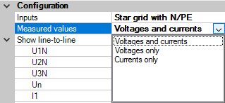
Measured values
Select which raw signals are available.
Based on the selection, the inputs for voltages or currents are displayed or hidden.
Show line-to-line
This option is only available in a star system. It activates the additional inputs for U12, U23 and U31.
If the additional inputs are not assigned to any signals, the central unit will calculate the signals and use them for the further calculations.
If signals are assigned, they will be the basis for calculations.
Nominal voltage
The nominal voltage for this grid, e.g.: 230 V
Mains signalling voltage
If this option is activated, the carrier frequency of the mains signalling voltage as well as the percentage signal level needs to be set for the grid.
You can find out the carrier frequency at your local energy supplier. The signal level usually lies between 1-2 %.
Units
The set units influence the calculated output values.
If large input signals are combined in a calculation, e.g. kV and kA, the output values can be set to a comprehensible dimension.
Standard generation
Enable currents
If Enable currents = TRUE, all current values are calculated additionally.
If “Only voltages” are selected under “Measured values”, the “Enable currents” option is not available.
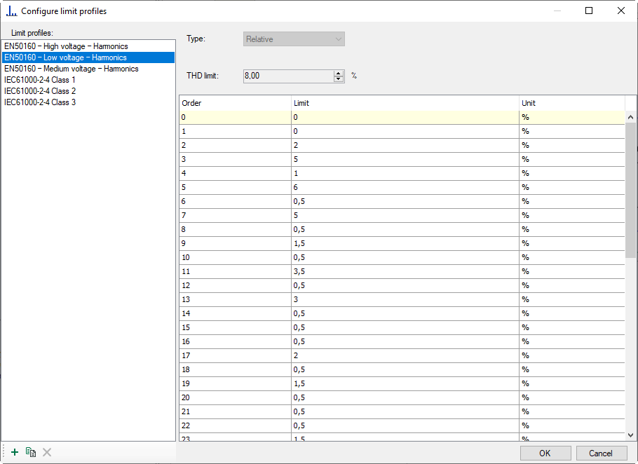
Configure limit profiles
Here you can create and manage limit profiles used in the Spectrum modules or triggers.
The predefined profiles can be used directly in relative spectra or triggers. To create a user-defined profile, click the button <+>. This allows creating profiles of the “relative” or “absolute” type.
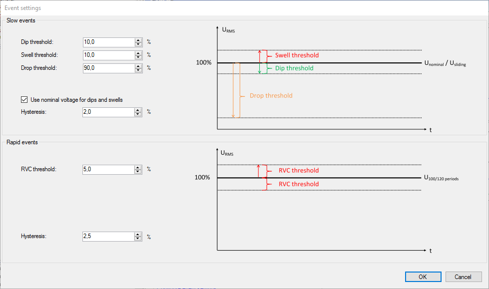
Configure event settings
You can configure in this dialog the settings for the single events such as voltage dip, voltage swell etc.
The values preset are taken from the standard IEC 61000-4-30 Ed. 3 class A.
Using the threshold values you can set the detection limit from which the corresponding event can be recognized. The hysteresis sets the point of time when the event can be considered as terminated.
Using the check box Use nominal voltage for dips and swells you can set if the threshold values and the hysteresis of the slow events refer to the nominal voltage or to a floating reference value.
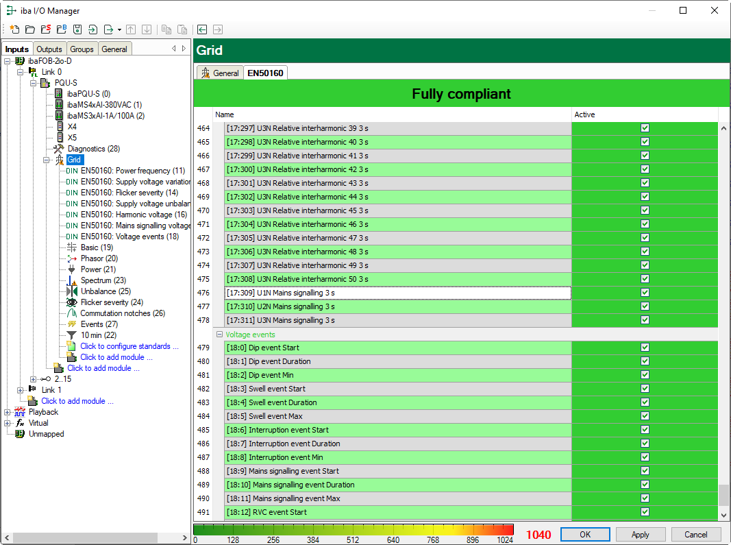
EN50160 tab
The EN50160 tab lists all signals calculated in the EN50160-compliant submodules. The message “Fully compliant” against a green background confirms compliance with the standard. If individual signals are disabled, the display changes to “Partially compliant” on a white background.
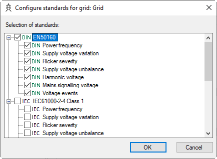
This tab is only displayed if you have configured the EN50160 standard by clicking “Click to configure standards...”.
