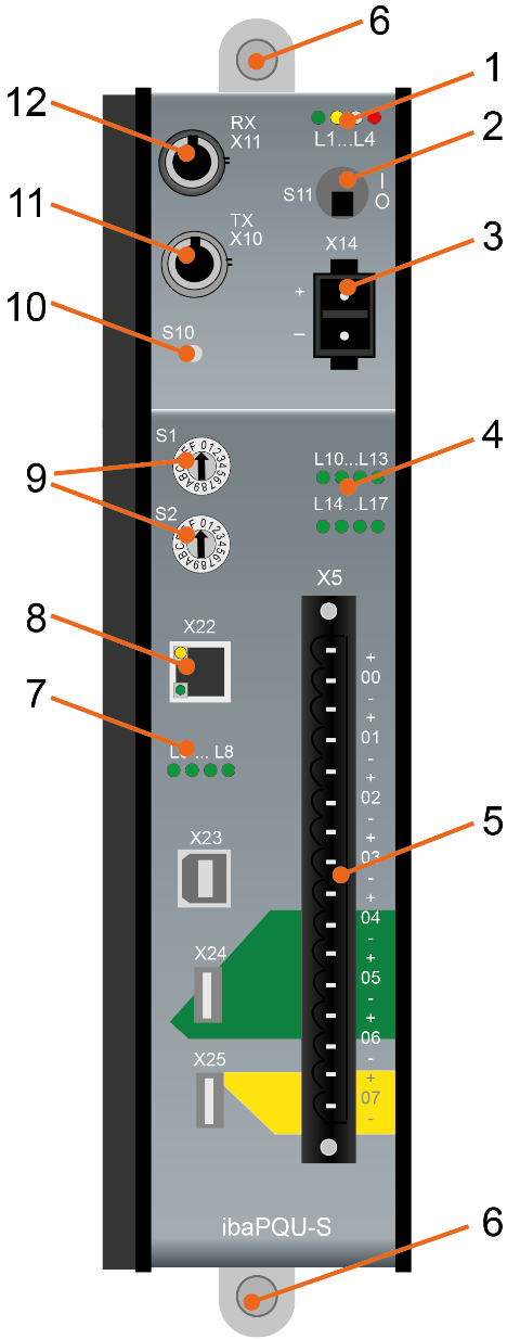
Here you will find the views and descriptions of the ibaPQU-S device.
Front view
|
1 |
Operating status indicator L1…L4 |
8 |
Network interface X22 (no function) |
|
2 |
ON/OFF switch S11 |
9 |
Rotary switches S1, S2 |
|
3 |
Connection power supply 24 V X14 |
10 |
System function push button S10 (no function) |
|
4 |
Indicators digital inputs L10…L17 |
11 |
Connection FO output (TX) X10 |
|
5 |
Connection for digital inputs X5 |
12 |
Connection FO input (RX) X11 |
|
6 |
Fixing screws |
X23 for service purposes only |
|
|
7 |
Indicators L5…L8 |
X24, X25 USB host interfaces for future functions |
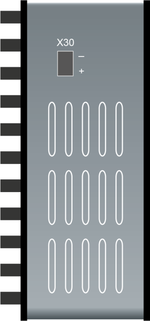
Bottom view
X30 buffer voltage connection 6 V…60 V DC

