To configure a module, select it in the tree structure.
All modules have the following setting options.
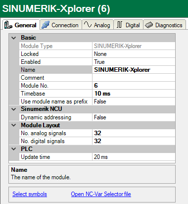
Basic settings
Module Type (information only)
Indicates the type of the current module.
Locked
You can lock a module to avoid unintentional or unauthorized changing of the module settings.
Enabled
Enable the module to record signals.
Name
You can enter a name for the module here.
Comment
You can enter a comment or description of the module here. This will be displayed as a tooltip in the signal tree.
Module No.
This internal reference number of the module determines the order of the modules in the signal tree of ibaPDA client and ibaAnalyzer.
Timebase
All signals of the module are sampled on this timebase.
Use module name as prefix
This option puts the module name in front of the signal names.
Sinumerik NCU
Dynamic addressing
Row and column values can be addressed dynamically. If this option is enabled, two additional columns are added to the signal grids: Row Source and Col Source. In these columns, you can configure the signal whose value should be used as row or column number. See also chapter Signal configuration
Module layout
No. analog signals/No. digital signals
Define the number of configurable analog and digital signals in the signal tables. The default value is 32 for each. The maximum value is 1000. The signal tables are adjusted accordingly.
Note |
|
|---|---|
|
Observe the maximum number of signals permitted by your base license for ibaPDA. |
|
Note |
|
|---|---|
|
Take into consideration that the number of signals, which are read by a CPU, influences the minimum achievable update cycle. The more signals acquired, the longer the achievable update time. |
|
PLC
Update time
Specifies the reference update time in which the data is requested from the PLC. During measurement, the real current update time may be higher than the specified value if the PLC needs more time to transmit the data. You can check in the connection table how fast the data is actually updated.
Check the diagnostic overview for measured update rates as overload will result in lost samples.
"Select symbols" link
Click on this link after the connection has been successfully established to configure the signals to be measured.
Link "Open NC-Var Selector file"
Click on this link to open the file browser in which you can select a variable file (*.var). All variables contained in the VAR file are added. You can create VAR files with the NC-VAR-Selector. The NC-VAR-Selector program is bundled with the Siemens SINUMERIK Toolbox for both STEP 7 and TIA Portal.