In the Analog or Digital tab, you configure the signals to be measured. In the General tab under Module Layout you define the length of the signal tables or the number of signals per table.
Note |
|
|---|---|
 |
Observe the maximum number of signals permitted by your license. |
Note |
|
|---|---|
|
Take into consideration that the number of signals, which are read by a CPU, influences the minimum achievable read cycle. The more signals recorded, the slower the reachable reading cycle. |
Selection of the signals to be measured
You have two options to select the signals to be measured:
-
In the module's General tab, click on the Add operands hyperlink.
The MELSEC Operand Constructor opens.
-
Click on a field in the Analog or Digital tab, click in a cell in the MELSEC Operand column.
The button <…> appears. Click the <…> button to open the MELSEC Operand Constructor.
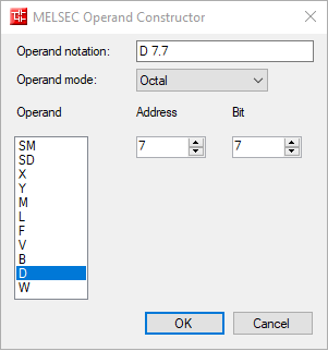

Using the MELSEC Operand Constructor, you can easily add analog and digital signals to the MELSEC-Xplorer module. Depending on which signal tab is selected (Analog or Digital) and the PLC type configured in the Connection tab (see Connection settings), a list of accessible operands is available. In the digital operand type list, the analog operand types are listed as well.
User interface of the MELSEC Operand Constructor
Operand mode
The following number systems are supported: octal, decimal and hexadecimal.
Address
Apart from the operand type, you also have to enter the address.
Bit
Since the digital operands are still analog data types in the PLC, you also have to specify the bit number you want to use for the digital signal.
The figure below shows an example of an Analog tab of a MELSEC-Xplorer module. Apart from the standard properties of an analog signal, there is a column for editing the MELSEC Operand. You can also configure the data type of the requested operand here. ibaPDA supports the following data types are supported: BYTE, INT, WORD, DINT, DWORD and FLOAT.
The Digital tab shows a similar grid for the digital signals.
