In the Analog and Digital tabs, the variables to be measured are configured.
The length of the signal table or the number of signals per table is determined in the general settings of the modules, module structure (see General Module Settings).
Note |
|
|---|---|
|
Observe the maximum permissible signal number based on your license. |
|
Note |
|
|---|---|
|
Take into consideration that the number of signals, which are read by a device, influences the minimum achievable read cycle. The more signals recorded, the slower the reachable reading cycle. |
|
Selection of measuring signals
You have two options to select the measuring signals:
-
Click on the Select symbols hyperlink in the General tab of the module.
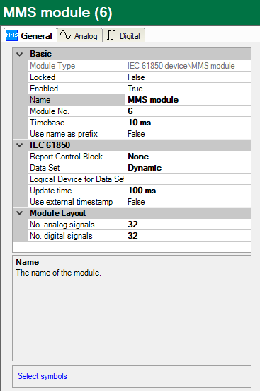
Use the mouse to click on the link and open the symbol browser.
-
Click on a field in the “Symbol” column in the Analog or Digital tab.

The icon ![]() will become visible. A click on the icon opens the symbol browser.
will become visible. A click on the icon opens the symbol browser.
If you open the symbol browser via the hyperlink in the General tab, all available signals are contained there. Depending on whether you select an analog or digital signal in the browser’s signal tree, the Analog or Digital tab will be opened in the background. If you add a signal, it will be inserted in the next open line of the matching signal table.
If you have selected “None” or “Dynamic” under Data Set in the general module properties, you will be shown a tree in the symbol browser with all logical devices, nodes and data objects of the server.
The table view shows the data attributes of the selected object. Use the <Offline> button to switch the system <Online>. The current values can then be shown here. In the event of error indications, see chapter Error messages.

If you have selected a preconfigured data set in the general module properties under Data Set in the symbol browser you will see a flat view of all of the assigned data objects of the data set.

You can select individual or several signals in the signal tree.
Click on <Add> to add them to the corresponding analog or digital signal table. If you select an individual signal, then the next signal is marked after clicking on <Add>. In this way, you can add several successive signals by pressing <Add> several times. You can also add a signal to the signal table by double clicking on the signal.
You can also search by symbol name in the Search tab of the symbol browser. The signal tree of the search result can be operated like the complete signal tree.
Note |
|
|---|---|
|
By means of the checkbox “Hide symbols with an unsupported datatype” you can hide all not supported data types. |
|
Description of the tables
The analog signals to be measured must be entered in the signal tables with the complete name (symbol) and the data type. This is done automatically when selecting via the symbol browser. You can assign any signal name.


The following data types are supported:
Special note for GOOSE module without selected GOOSE control block

If no GOOSE control block is used (MMS communication is not supported), then the signal is not assigned via the symbol, but via the index of the data in the telegram. The data type must also be selected manually.
Index 0 means the first element in the dataset, index 1 the second element, ... . If an element in the dataset is a structure, it is also necessary to define which element from the structure should be used. This is done via "Index,Subindex".
Example: Index 4,2 means the fifth element in the dataset. This is a structure, the third subelement of the structure is used.