To configure a module, select it in the tree structure.
All modules have the following setting options.
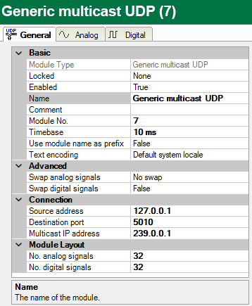
Basic settings
Module Type (information only)
Indicates the type of the current module.
Locked
You can lock a module to avoid unintentional or unauthorized changing of the module settings.
Enabled
Enable the module to record signals.
Name
You can enter a name for the module here.
Comment
You can enter a comment or description of the module here. This will be displayed as a tooltip in the signal tree.
Module No.
This internal reference number of the module determines the order of the modules in the signal tree of ibaPDA client and ibaAnalyzer.
Timebase
All signals of the module are sampled on this timebase.
Use module name as prefix
This option puts the module name in front of the signal names.
Text encoding
You can select the type of text encoding or the code page here for a correct interpretation and display of the received text data for inputs as well as of the text data to be sent for outputs. Available for selection are, beside system locale according to the Windows system settings (default) and UTF-8 Unicode, all other encodings.
Advanced
Swap analog signals/Swap digital signals
Option to change the order of the byte evaluation. The swap mode to be selected depends on the swap mode of the signal source.
Connection
Source address, Destination port
With these two values the connection to a certain controller can be clearly identified. The port has to be within the port range defined for the interface and has to be enabled for the firewall (see General interface settings).
Multicast IP address (only for module type Generic Multicast UDP)
Specify here the multicast address used by the controller to send data to ibaPDA using Multicast. The multicast addresses are in the range from 224.0.0.0 through 239.255.255.255.
Note |
|
|---|---|
 |
The only difference between the multicast and unicast modules is the destination IP address on side of the sending controller. For the unicast modules this is the IP address of the ibaPDA server PC. For the multicast modules, this is a multicast address. There are the following limitations: The combination of source address and destination port number of a multicast module must be different than that combination of all the other unicast and multicast modules. So, you cannot have one sender sending to different multicast addresses with the same port number. You also cannot have a sender that is sending both unicast and multicast messages to the same port number. |
Module Layout
No. analog signals, No. digital signals
Define the number of configurable analog and digital signals in the signal tables. The default value is 32 for each. The maximum value is 6056 for analog signals and 16384 for digital signals. The signal tables are adjusted accordingly. Note that the total amount of data must not exceed 16384 bytes for analog and digital signals together.
Other documentation |
|
|---|---|
 |
You can find further information in the ibaPDA manual. |