The data to be measured are selected on the controller side by mapping the signals in the datagram, which is cyclically sent to ibaPDA
Analog and Digital tab
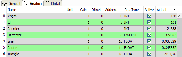
You can assign name, unit, address and data type or bit number to the analog and digital signals. Moreover, you can enable or disable the signals.
Other documentation |
|
|---|---|
|
For a description of the columns, please see the ibaPDA manual. |
|
Specific columns for Generic TCP modules:
Address
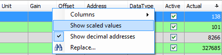
The address indicates the offset of the first byte of this value within the user data telegram. You can enter the offset as hexadecimal or decimal value by selecting the desired setting in the context menu.
The digital signals are addressed via the Address and Bit no. (0 – 31) columns.
DataType (analog signals only)
ibaPDA supports the following data types: BYTE, WORD, DWORD, SINT, INT, DINT, LINT, FLOAT, DOUBLE, S5 FLOAT and STRING[32].
The address range depends on the data type. Hence, after changing the data type, you possibly have to adjust the address entries.
Note |
|
|---|---|
|
The module Generic TCP supports the acquisition and processing of strings as text signals. Therefore, you can select the datatype STRING[32] in the Analog tab. In order to convert a text signal or to split it up into several text signals use the Text splitter module on the Analytics tab. |
|
Tip |
|
|---|---|
|
You can use the automatic fill function in the columns, see ibaPDA manual. |
|