The signals can be configured in the I/O Configurator of ibaLogic-V5.
-
Open the I/O Configurator in the Tools – I/O Configurator menu.
-
Click on the <Update hardware> button.
ibaLogic-V5 detects the module.
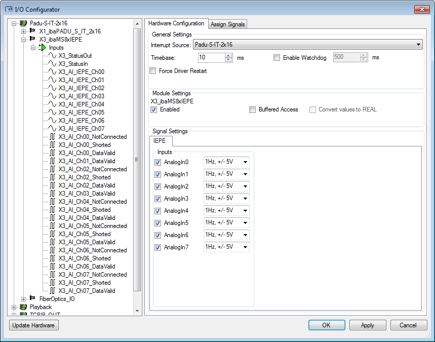
The analog input channels and the status signals are displayed in the Inputs tab.
-
Select the input mode from the selection menu, see Analog inputs.
-
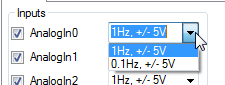
IEPE mode is the fixed setting for channels 0, 2, 4 and 6, but the filter can be selected:
-
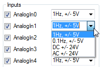
Mode selection for the channels 1, 3, 5 and 7:
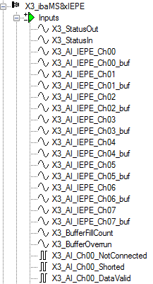
If Buffered Access is enabled, you can see additional input and output signals.
-


Note |
|
|---|---|
|
You need to apply the buffered access by clicking on the <Apply> button. Only then, you will see additional signals in the signal tree that can be configured as output or input resources. |
|
|
Signal |
Meaning |
|---|---|
|
Inputs |
|
|
AI_IEPE_Ch[00…07] |
Analog input signals |
|
AI_Ch[00…07]_NotConnected |
Status signal indicates, whether there is a broken line or a channel is not connected (only in IEPE mode) |
|
AI_Ch[00…07]_Shorted |
Status signal indicates a short circuit (only in IEPE mode) |
|
AI_Ch[00…07]_DataValid |
Status signal indicates, whether the data is valid |
|
StatusIn |
Status information about the plugged input module (for output module without function): 0 = module not initialized 1 = module running >1 = error (e.g. Module cannot be initialized) |
|
StatusOut |
Status information about the plugged module (for input module without function): 0 = module not initialized 1 = module running >1 = error (e.g. Module cannot be initialized) |
|
Additional input signals for buffered access |
|
|
AI_IEPE_Ch[00…07]_buf |
Input buffer of analog signals: |
|
BufferFillCount |
Counter, when buffer is filled |
|
BufferOverrun |
Counter for Buffer-overrun |
|
Additional output signals for buffered access |
|
|
BufferSize |
Buffersize |
|
SubSampling |
Subsampling of the signals |