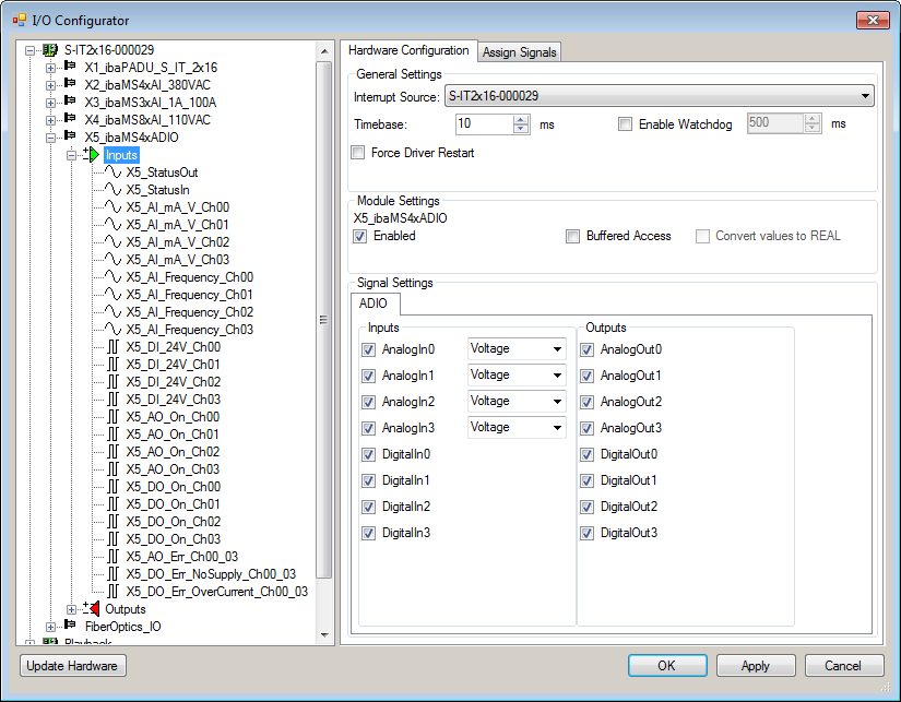
The signals can be configured in the I/O Configurator of ibaLogic-V5.
-
Open the I/O Configurator in the Tools – I/O Configurator menu.
-
First, click on the <Update Hardware> button.
-
ibaLogic detects the module.
-
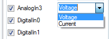
In the drop-down menu you can select between voltage or current input.


If Buffered Access is enabled, you can see additional input and output signals.
Note |
|
|---|---|
|
You need to apply the Buffered Access by clicking on the <Apply> button. Only then, you will see additional signals in the signal tree that can be configured as output or input resources. |
|
|
Signal |
Meaning |
|---|---|
|
Inputs |
|
|
AI_mA_V_Ch[00…03] |
Analog input signals |
|
AI_Frequency_Ch[00…03] |
Calculated power frequencies |
|
AO_On_Ch[00…03] |
Analog output active |
|
DI_24V_Ch[00… 03] |
Digital input signals |
|
DO_On_Ch[00…03] |
Digital output active |
|
AO_Err_Ch00…03 |
Error of the quad root of analog outputs |
|
DO_Err_NoSupply_Ch00_03 |
Load voltage error of a quad root of digital outputs |
|
DO_Err_OverCurrent_Ch00_03 |
Quad root of the digital outputs is in error state due to overcurrent |
|
StatusIn |
Status information about the plugged input module (for output module without function): 0 = Module not initialized 1 = Module running >1 = Error (e.g. module cannot be initialized) |
|
StatusOut |
Status information about the plugged module (for input module without function): 0 = Module not initialized 1 = Module running >1 = Error (e.g. module cannot be initialized) |
|
Outputs |
|
|
AO_10V_Ch[00… 03] |
Analog output signals |
|
AI_DigitalFilterMode |
Enables the digital anti-aliasing filter in addition to the analog anti-aliasing filter (if enabled) |
|
AI_AntiAliasingFrequency |
Setting of the cut-off frequency of the digital anti-aliasing filter |
|
AI_PwrFreqMode_Ch[00…03] |
Setting of the measuring interval for power frequency measurement (per channel) |
|
AI_EnableFilter_Ch[00…03] |
Enables the analog anti-aliasing filters (per channel) |
|
AO_ResetError_Ch00…03 |
Output signal for resetting a hardware error |
|
DO_24V_Ch[00… 03] |
Digital output signals |
|
DO_ResetError_Ch00_03 |
Output signal for resetting a hardware error |
|
DI_DebType_Ch[00…03] |
Debounce filter for digital signals |
|
DI_DebTime_Ch[00...03] |
Debounce time for the respective digital signal |
|
Additional input signals for buffered access |
|
|
AI_mA_V_Ch[00…03]_buf |
Input buffer of analog input signals |
|
AI_Frequency_Ch[00…03]_buf |
Input buffer of calculated power frequencies |
|
DI_24V_Ch[00…03]_buf |
Input buffer of digital input signals |
|
AO_On_Ch[00…03]_buf |
Input buffer for analog outputs “active” |
|
DO_On_Ch[00…03]_buf |
Input buffer for digital outputs “active” |
|
AO_Err_Ch00… 03_buf |
Input buffer for error signals when quad root of ana-log outputs is in error state |
|
DO_Err_NoSupply_Ch00_03_buf |
Input buffer for error signals when error in the load voltage of a quad root of digital outputs |
|
DO_Err_OverCurrent_Ch00_03_buf |
Input buffer for error signals when quad root of the digital outputs is in error state due to overcurrent |
|
BufferFillCount |
Counter, when buffer is filled |
|
BufferOverrun |
Counter for buffer overrun |
|
Additional output signals for buffered access |
|
|
BufferSize |
Buffersize |
|
SubSampling |
Subsampling of the signals |