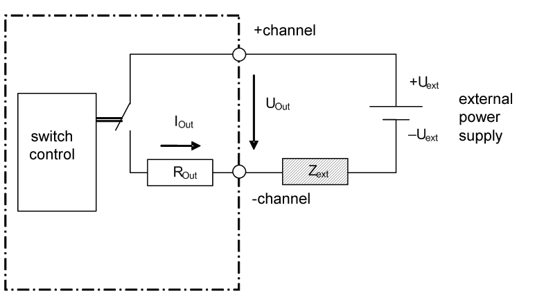
The circuit is designed as P switch (positive voltage).
The connected load Zext is connected to –Uext and switched on +Uext by means of the controllable switch (load switch) in the output channel. This typical circuit is shown schematically in the following figure.
