The description is based on the example of the ibaMS16xAI-10V module. The signals can be configured in the I/O Configurator of ibaLogic-V5.
-
Open the I/O Configurator in the Tools – I/O Configurator menu.
-
Click on the <Update hardware> button.
ibaLogic-V5 detects the module.
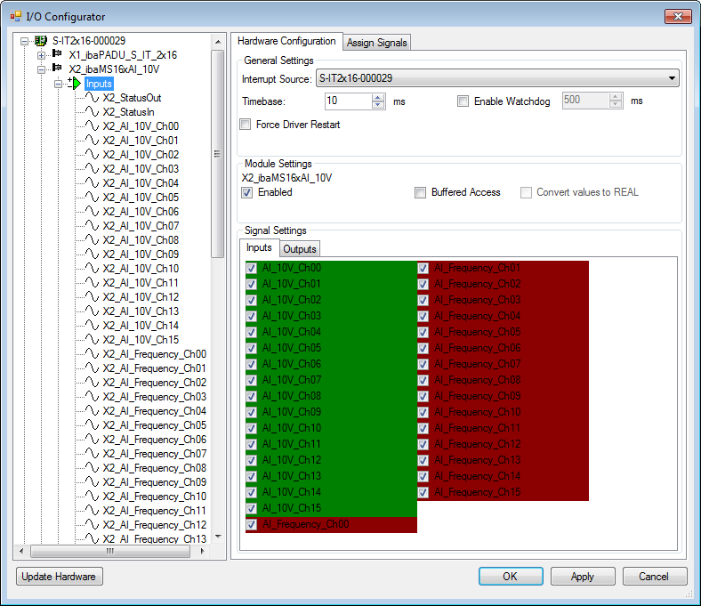
The analog input channels and the power frequency signals are displayed in the Inputs tab.
-
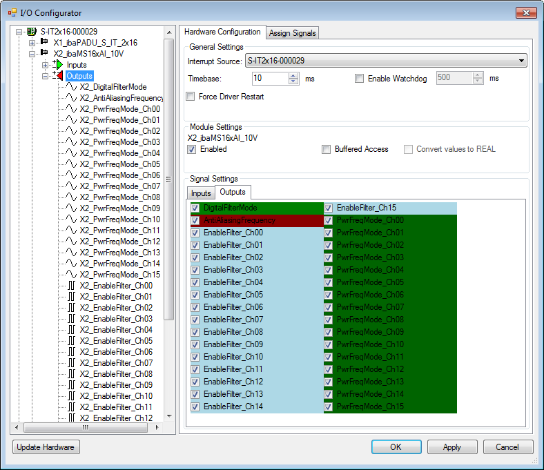
The filters are enabled and configured by means of signal outputs as well as the mode for power frequency measurement.
If Buffered Access is enabled, you can see additional input and output signals.


Note |
|
|---|---|
|
You need to apply the buffered access by clicking on the <Apply> button. Only then, you will see additional signals in the signal tree that can be configured as output or input resources. |
|
|
Signal |
Meaning |
|---|---|
|
Inputs |
|
|
AI_10V_Ch[00…15] |
Analog input signals |
|
AI_Frequency_Ch[00…15] |
Calculated grid frequencies |
|
StatusIn |
Status information about the plugged input module (for output module without function): 0 = module not initialized 1 = module running >1 = error (e.g. Module cannot be initialized) |
|
StatusOut |
Status information about the plugged module (for input module without function): 0 = module not initialized 1 = module running >1 = error (e.g. Module cannot be initialized) |
|
Outputs |
|
|
DigitalFilterMode |
Activates the digital anti-aliasing filter in addition to the analog anti-aliasing filter (if activated) |
|
AntiAliasingFrequency |
Setting of the cutoff frequency of the digital anti-aliasing filter |
|
EnableFilter_Ch[00…15] |
Enables the analog antialiasing filters (per channel) |
|
PwrFrqMode_Ch[00…15] |
Setting of the measuring interval for power frequency measurement (per channel) |
|
Additional input signals for buffered access |
|
|
AI_10V_Ch[00…15]_buf |
Input buffer of analog signals: |
|
AI_Frequency_Ch[00…15]_buf |
Input buffer of calculated grid frequencies |
|
BufferFillCount |
Counter, when buffer is filled |
|
BufferOverrun |
Counter for Buffer-overrun |
|
Additional output signals for buffered access |
|
|
BufferSize |
Buffersize |
|
SubSampling |
Subsampling of the signals |