After configuring the HD data store, measuring locations have to be defined. The associated signals can then be assigned to the measuring locations with the appropriate recording profile.
For a length-based data store, multiple measuring locations (ML Measuring Location) can be defined. At least one measuring location has to be defined. Measuring locations serve for the grouping of measuring signals that are created in the plant/in the process at the same place and which have a product reference.
Refer also to the introducing example in chapter Length-based data store.
The general rule is:
All signals of a measuring location have to use the same length unit and the same maximum speed in the plant. Therefore, those values will only be set once per data store.
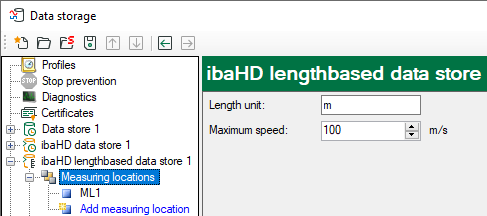
Mark the branch “Measuring Locations" with the mouse and enter the length unit and maximum speed here. The length unit only serves for a correct labeling, e.g. of the axes. The maximum speed is used for a reasonable limitation of the actual speed, to limit the speed, that is used to calculate the length data, to the maximum value in case of a malfunction.
A first measuring location (ML1) exists by default. Mark the measuring location with the mouse and continue the configuration of the measuring location.
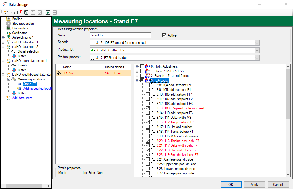
In this dialog, make the following settings:
-
-
Name the measuring location
-
Select control signals for the measuring location
-
Select the signals to be measured and their recording profile
-
Name
Enter a unique name for this measuring location to be able to identify it. The name of the measuring location is a part of the signal ID for the signal references in the ibaPDA client. A later renaming of a measuring location could lead to invalid signal references in the ibaPDA client.
Speed
Select the speed signal that transfers the speed measured at this measuring location.
Product ID
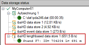
For the product ID you need a text signal. With this text signal the product is denominated, which is currently located at this measuring location. During the measurement, the ID is shown in the window “Data storage status”:
Product present
Select a digital signal here, that is exactly TRUE at the moment the product is located at the measuring location (e.g. of photoelectric cell, proximity sensor, material tracking etc.) With the edges of this signal, the length calculation is also triggered.
With the rising edge, the initialization of a new product is started, i.e. the text signal selected under product ID is read. Furthermore, the speed signal for the length calculation, starting from length 0, is integrated from this moment on. With the falling edge of the signal, the length calculation and the data storage are terminated. A gap (fixed width) is inserted in the HD trend graph display.
If the signal is FALSE, the ibaHD-Server does not store data for the concerned measuring location.
Selecting signals
First, mark the required recording profile in the left field, which should be used to store the samples. Thereafter, select the signals from the signal tree on the right that you want to store and that belong to this measuring location.
Note |
|
|---|---|
|
A signal can always be assigned to only one measuring location. If you assigned one signal to several measuring locations, an error message will appear at the verification of the data store configuration.
|
|
Tip |
|
|---|---|
|
If you need a signal at several measuring locations, duplicate the signal with the help of the virtual signals and then assign them to the measuring locations. |
|


