PCI cards
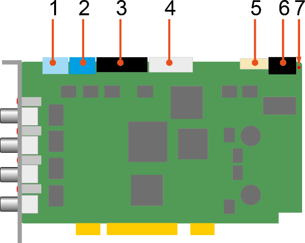
Example ibaFOB-4i-D
|
1 |
SYNC: synchronization of iba cards (Sync-IRQ connector) |
|
2 |
+5 V: power supply for Sync-i/Sync-o |
|
3 |
TX-OUT: ibaFOB-4o (outputs) |
|
4 |
TX-MIRROR: ibaFOB-4o (mirrored inputs) |
|
5 |
JTAG: Service interface |
|
6 |
DCF77 & ALARM: spare connector, prepared for future extensions |
|
7 |
ALARM STATUS: Debug LED |
PCI Express cards (HW version A)
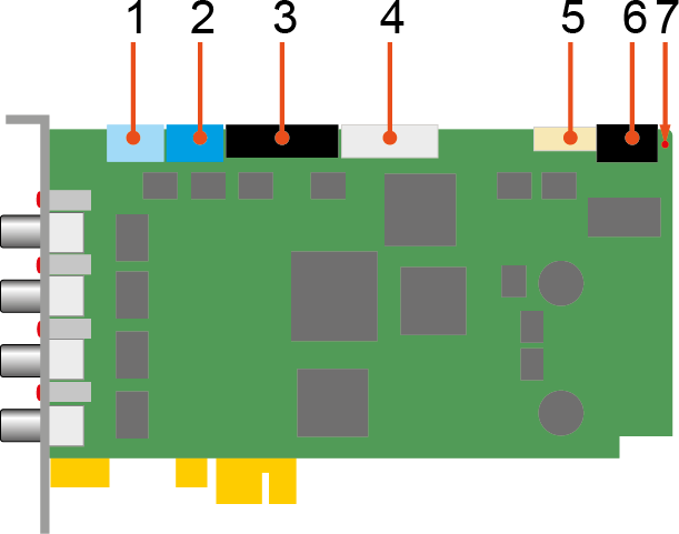
Example ibaFOB-4i- Dexp
|
1 |
SYNC: synchronization of iba cards (Sync-IRQ connector) |
|
2 |
+5 V: power supply for Sync-i/Sync-o |
|
3 |
TX-OUT: ibaFOB-4o (outputs) |
|
4 |
TX-MIRROR: ibaFOB-4o (mirrored inputs) |
|
5 |
JTAG: Service interface |
|
6 |
DCF77 & ALARM: spare connector, prepared for future extensions |
|
7 |
ALARM STATUS: Debug LED |
PCI Express cards (HW version B)
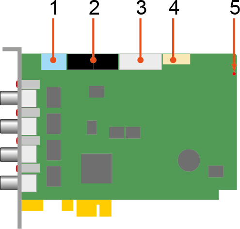
Example ibaFOB-4i- Dexp
|
1 |
SYNC: synchronization of iba cards (Sync-IRQ connector) |
|
2 |
TX-OUT: ibaFOB-4o (outputs) |
|
3 |
TX-MIRROR: ibaFOB-4o (mirrored inputs) |
|
4 |
SERVICE: Service interface |
|
5 |
STATUS: Debug LED |
Maximum distance of fiber optic connections
The maximum distance of fiber optic connections between 2 devices depends on various influencing factors. This includes, for example, the specification of the fiber (e. g. 50/125 μm, 62.5/125 μm, etc.), or the attenuation of other components in the fiber optic cable plant such as couplers or patch panels.
However, the maximum distance can be estimated on the basis of the output power of the transmitting interface (TX) or the sensitivity of the receiving interface (RX). A model calculation can be found in chapter Example for FO budget calculation.
The specification of the transmitter's output power and the receiver's sensitivity of the fiber optic components installed in the device can be found in the technical data in chapter Main data ibaFOB-D/ibaFOB-Dexp under "ibaNet interface".


