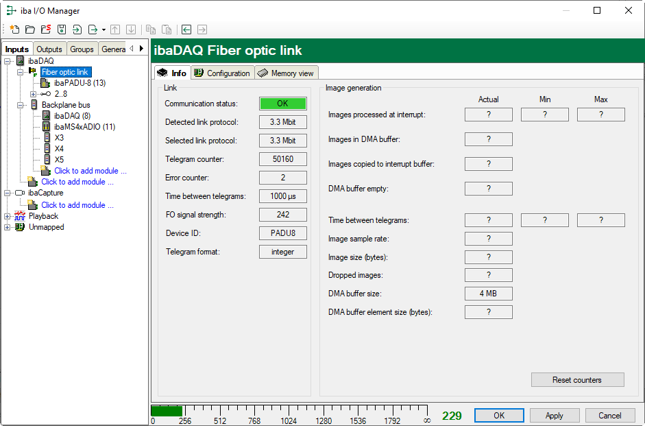
”Link” area
Communication status
OK when FO communication is working properly. This means that the telegrams received correspond to the mode configured on the link. The transmission mode is determined by the device (module) connected to the FO interface. For example, if an ibaPADU-8AI is connected, the link will be set to 3Mbit mode. If an ibaPADU-D-8AI is connected, the link will be set to 32Mbit Flex.
Detected link protocol
This is the detected transmission protocol. Possible values: 2Mbit, 3Mbit, 5Mbit, 32Mbit, 32Mbit Flex or "?" (no device connected).
Selected link protocol
This is the transmission protocol set for this FO interface. It is determined by the attached module.
Telegram counter
Counter of correctly received telegrams
Error counter
Counter of received faulty telegrams (e.g. checksum error). If this counter reading changes, the fiber optic communication is not correct.
Time between telegrams
The time interval between the last 2 correctly received telegrams.
FO signal strength
This is the difference between the maximum value and the minimum value received from the FO unit. This can be a maximum 255. The higher this value the stronger the FO input signal.
Device ID
The ID of the last device in an FO series connection at this FO interface.
Telegram format
This is the format of the analog data transferred in the telegram. Possible formats are "Integer", "Real" and "S5 real".
“Image generation” area
The information on the right side of the dialog describes the image generation (process image). An image is a collection of bytes that the card writes into the PC system memory via DMA. This image contains all data of the measured signals on that link.
The following list explains the image generation information:
Images processed at interrupt
These counters show how many images were available in the DMA buffer when the last interrupt fired. This should normally correspond with the interrupt time divided by the image sampling rate.
Images in DMA buffer
This is the number of images available in the DMA buffer. This number should remain constant. If this number increases, the system does not work correctly. This can be a missing interrupt for example.
Images copied to interrupt buffer
This counter shows how many images have been retrieved from the DMA buffer and have been processed by ibaPDA. This counter should count up continuously.
DMA buffer empty
This counter increments each time the DMA buffer is empty when the interrupt fires. If this is the case, the driver will set all signal values of the respective port to zero (0). This may happen if the FO link is disconnected.
Time between telegrams
The time between the last 2 correctly received telegrams. This is the same value as the time in the FO communication information but the driver maintains the minimum and maximum values. The differences between min. and max. value should not deviate significantly from each other.
Image sample rate
The rate at which the card writes images to the DMA buffer. It should be greater than or equal to the fastest acquisition rate of the modules connected to this link.
Image size
This is the image size in bytes. If you multiply the image size with the image sample rate, you know how many bytes per second are transferred by this link over the PCI bus.
Dropped images
This counter increments when the card’s DMA FiFo is full and additional images are added. If this happens then something is seriously wrong. The card cannot transfer images over the PCI bus.
DMA buffer size
Size of the DMA buffer for this interface.
DMA buffer element size (bytes)
Size of the elements in the DMA buffer (in bytes).
