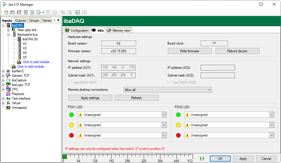
In the Info tab, make the hardware settings and network settings for the "ibaDAQ" module. Here you can assign signals to the LEDs PDA1 and PDA2.
Hardware settings
Information on the card version and firmware version of the internal ibaFOB card as well as information on the card clock
<Write firmware>
With this button it is possible to perform firmware updates, see Firmware update.
Note |
|
|---|---|
|
This process may take several minutes and must not be interrupted. After an update, the device driver and the ibaPDA service will restart automatically. |
|
<Reboot device>
Click this button to restart the device.
Network settings
The settings of IP address, subnet mask and DHCP server are only available if the rotary switch S1 is set to "0".
Use DHCP
Here you can select separately for the two network interfaces X21 and X22 whether a DHCP server is used or not.
IP address
Here you can enter a user-defined IP address for the network interfaces X21 and X22. The option "Use DHCP server" must not be enabled to do so.
Subnet mask
Enter the suitable subnet mask for your network here.
The option "Use DHCP server" must not be enabled to do so.
Note |
|
|---|---|
|
It is also possible to select different address assignment methods for the two interfaces X21 and X22, e. g. DHCP active for X21 and a fixed IP address for X22, see Rotary switch S1. |
|
Remote desktop connections
Here you can allow or deny remote desktop connections. Possible settings:
-
Disabled
-
Allow all
-
Only secure connections
<Apply settings>
Click <Apply settings> to apply the network settings in the device.
<Refresh>
Click <Refresh> to update the network settings.
Note |
|
|---|---|
|
Please remember to assign the corresponding user authorizations when setting up the remote desktop connection for the first time. This is only possible directly at the device and not via the ibaPDA client. If you run ibaDAQ in a domain, you may ask the IT department to assign the authorizations. |
|
PDA1/2 LED
Here you can assign signals to the LEDs PDA1 and PDA2. 3 colors (green, yellow, and red) are available for each LED. Select one input signal respectively from the drop-down menu. If the corresponding signal applies, the LED will light up in the configured color.

