|
1 |
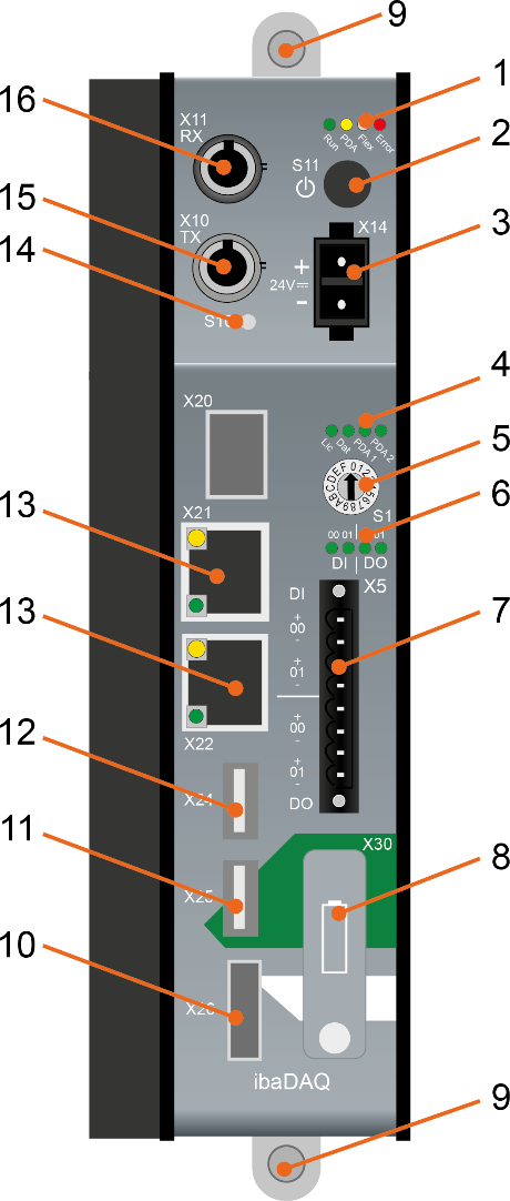
Operating state indicator |
10 |
Monitor connection X26 |
|
2 |
ON/OFF switch S11 |
11 |
USB 2.0 port X25 |
|
3 |
Connection power supply 24 V X14 |
12 |
USB 3.0 port X24 |
|
4 |
Indicator (operating status, user-defined) |
13 |
Network interfaces X22 and X21 |
|
5 |
Rotary switch S1 |
14 |
System function push button S10 |
|
6 |
Indicator of digital inputs and outputs |
15 |
Connection FO output (TX) X10 |
|
7 |
Connection of digital inputs and outputs X5 |
16 |
Connection FO input (RX) X11 |
|
8 |
Battery compartment X30 |
||
|
9 |
Fixing screws |
X20, SFP port for future functions |
|
