Each component group is made up of individual components. New components can be added to existing component groups by dragging them from the library to the plant tree using drag & drop. The same function can also be used to replace existing components. This is particularly useful if you have used a pre-defined aggregate template, for example.
The templates contain dummy roller bearings, as the precise bearing types are not yet known. To replace the dummy, the correct bearing is selected from the library and dragged to the dummy bearing. All relevant component parameters are then automatically changed.
The bearings are displayed separately from the remaining components in the library.
The system provides templates containing pre-defined characteristic values for the following components:
-
Gear
-
Roller bearing
-
Fan
-
Coupling
-
Pump impeller
-
Pulley
-
Rotor blade
-
Roll
-
Stator/Rotor (electric motor); Note: Only supported to ensure back compatibility with existing configurations; component can no longer be created as a new item.
Settings for a component in the detail window
General tab
ID
This value is generated automatically by the database and cannot be changed.
Order
This value indicates the order of the display within the same level of the plant tree.
Name
The name of the asset (e.g. plant, aggregate group, aggregate, etc.) can be changed here.
Comment
The Comment field is used to enter comments about an asset. The input field can be enlarged by dragging (bottom right).
Position
Specifies the position of a component on the shaft.
The following positions are possible:
-
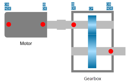
Centered position [CP]: Indicates the location of a component (e.g. bearing) in the center of the shaft.
-
Doubleside drive end [DDE]: Indicates a component or system, which has two drive or non-drive ends, e.g. a garbox with two output shafts.
-
Drive end [DE] / Inboard [IB]: Indicates the side where the load is tapped or applied. For motors this is referred to as A-side. For gearboxes it is the side of the input shaft, which applies the load to the gearbox.
-
Non drive end [NDE] / Outboard [OB]: Indicates the opposite side to the load. For motors this is referred to as B-side. For gearboxes this is the side where the load leaves the gearbox.
-
Without drive end [WDE]: Indicates a variant without input or ouput shaft, e.g. a pully or impeller with no motor shaft.
Sensor
Here, you can select the sensor that will be used to monitor this component.
The dropdown list contains all sensors assigned to the higher-level aggregate.
List of trends belonging to the individual components:
|
Component |
Trend |
|---|---|
|
Bearing |
FFT inner race (FFT = Fast Fourier Transformation for detection of frequency components) |
|
FFT outer race |
|
|
FFT rolling |
|
|
FFT cage |
|
|
ENV inner race (ENV = Envelope; envelope curve analysis) |
|
|
ENV outer race |
|
|
ENV rolling |
|
|
ENV cage |
|
|
Coupling |
FFT coupling |
|
Fan blade |
Fan blade |
|
Gear |
Gear mesh (tooth engagement frequency) |
|
Gear damage |
|
|
Gear wear |
|
|
Pulley |
FFT belt |
|
ENV belt |
|
|
Pump impeller |
Impeller |
|
Roll |
FFT roll |
|
Roll imbalance |
|
|
Rotor blade |
Rotor blade |
|
Shaft |
Shaft level |
|
Imbalance |
|
|
Local errors |
|
|
Stator/Rotor1 |
Stator defect |
|
Rotor defect conductor bars |
|
|
Rotor defect operating frequency |
Parameters
Different values can be set under Parameters depending on the component.
Below is a list of setting options for each component, along with the calculated frequencies:
|
Component |
Parameter [unit] |
Comment |
|---|---|---|
|
Gear |
Number of teeth [-] |
|
|
Tooth engagement frequency [Hz] |
Read only |
|
|
Stator/Rotor2 |
Motor slip [-] |
Entry 0-1 => 1 is 100% |
|
Number of pole pairs [-] |
||
|
Number of rotor bars [-] |
||
|
Power line frequency [Hz] |
||
|
Operating frequency [Hz] |
Read only |
|
|
Bar pass frequency [Hz] |
Read only |
|
|
Motor slip frequency [Hz] |
Read only |
|
|
Bearing |
Inner race defect frequency [Hz] |
Read only |
|
Outer race defect frequency [Hz] |
Read only |
|
|
Ball defect frequency [Hz] |
Read only |
|
|
Cage defect frequency [Hz] |
Read only |
|
|
Fan |
Number of fan blades [-] |
|
|
Fan blade pass frequency [Hz] |
Read only |
|
|
Coupling |
Number of claws [-] |
|
|
Coupling element pass frequency [Hz] |
Read only |
|
|
Pump blades |
Number of pump blades [-] |
|
|
Pump blade pass frequency [Hz] |
Read only |
|
|
Pulley |
Belt diameter [m] |
|
|
Belt length [m] |
||
|
Pulley frequency [Hz] |
Read only |
|
|
Rotor blade |
Number of rotor blades [-] |
|
|
Rotor blade pass frequency [Hz] |
Read only |
|
|
Roll |
Roll diameter [m] |
|
|
Roll frequency [Hz] |
Read only |
Plant links
Shows the shaft on which the component is located.
