On plants that operate in two or more different operating modes, e.g. rolling and calibration, it can be useful to use trend filters. A trend filter enables filter areas to be defined that filter the trend based on a filter signal. For example, the filter signal can output the value 1 for calibration mode and 2 for rolling mode. The advantage is that this enables different limits to be set for a characteristic value for the different filter areas.
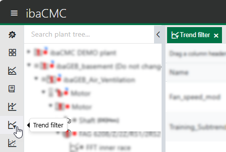
To obtain an overview of the available trend filters and to define new trend filters, open the trend filter view by clicking on the corresponding icon in the menu bar:
Filter signal
The filter signal can be a sensor or a TCP/IP channel. This signal is used as the input signal for the filter areas.
Note:
For TCP channels and AI or DI sensors, the AVG trend is used. For IEPE or ICP sensors, the peak-to-peak trend is used as the filter signal.
Filter areas
At least two filter areas are required. The first filter area runs from minus infinity to the set value. All subsequent areas have the maximum value of the previous set filter area as their minimum. Filter areas can be ignored so that no data is acquired in those areas.
Default filter area
One filter area must be selected as the default. This is used by default when loading the trend.
Assignment
After definition, the trend filter can be assigned to one or more components/sensors. After assignment of the trend filter, the trends for the components/sensors have multiple filtered trends in the trend analysis.