An analog value (e. g. a temperature scaled with FC105 from S7 standard library) is to be transferred as a REAL variable from S7-PLC to ibaBM-DP and acquired with ibaPDA.

Step 1: FO connecting and cabling
As ibaPDA is a passive application and thus only reads data from the PROFIBUS, the modes 0, 1 and 3 are available.
-
Connect the FO output (TX) on the ibaBM-DP with a FO input on the ibaFOB card in the ibaPDA computer.
-
Start the ibaPDA software and define a module “ibaBM-DP-64” in the I/O Manager of ibaPDA.
-
In the ibaPDA I/O Manager, mark the corresponding link under the ibaFOB card in the signal tree.
Even if the ibaBM-DP device is not yet connected to the PROFIBUS, valid telegrams are already sent to ibaPDA via fiber optic cables. Using the diagnostics function of ibaPDA you should be able to watch the telegram counter running.
As soon as the connection between the DP master and both slaves of ibaBM-DP has been established the “Bus” LED should light yellow and the “Active” LED white.
Step 2: GSD file installation and hardware configuration
-
Start the “HW Config” tool in the current S7 project and install the GSD file with name ibaF04n3.gsd
-
In the web interface of the ibaBM-DP, set the operating mode to mode 3 (PDA 28 Reals).
-
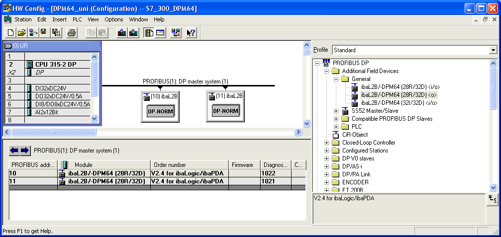
Open the “PROFIBUS DP” folder in the hardware catalog of "HW Config".
-
Connect an “ibaDPM64” module with the PROFIBUS line per drag & drop and set an DP address (in the example 10) for this module.
Note

The same address has to be set in the web interface of ibaBM-DP!
-
If you want to use both slaves on ibaBM-DP connect another module with the PROFIBUS line and assign in “HW Config” the other DP address set in the web interface.

Step 3: Establishing a connection to the DP
-
Connect the left DP interface on ibaBM-DP with the DP interface of your S7-PLC.
-
If ibaBM-DP is the last device on the DP line, then also activate the terminating resistor in the PROFIBUS connector.
-
Download the system data to the S7-PLC with HW Config and start the PLC.
As soon as the connection between the DP master and the ibaBM-DP slaves has been established the “Bus“ LED should light yellow and the “Active” LED white.
Step 4: S7 test program
-
Generate a DB11 (or any free DB number) in your S7 project.
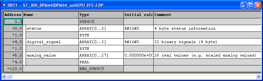
DB11 contains 120 byte data for ibaBM-DP.
-
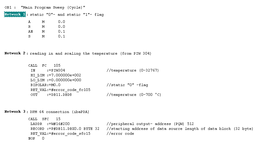
Define the local variables and call FC105 and SFC15 (both blocks from the S7 standard library) in OB1.
Other FCs are also possible.
The scaled temperature (0.0 °C to 700.0 °C) is saved as a REAL value in DB11.DBD8 (in the 1st memory area for analog signals).
Example for transfer of 32 bytes of consistent data from S7 PLC (DB11) to ibaBM-DP with SFC15:
-
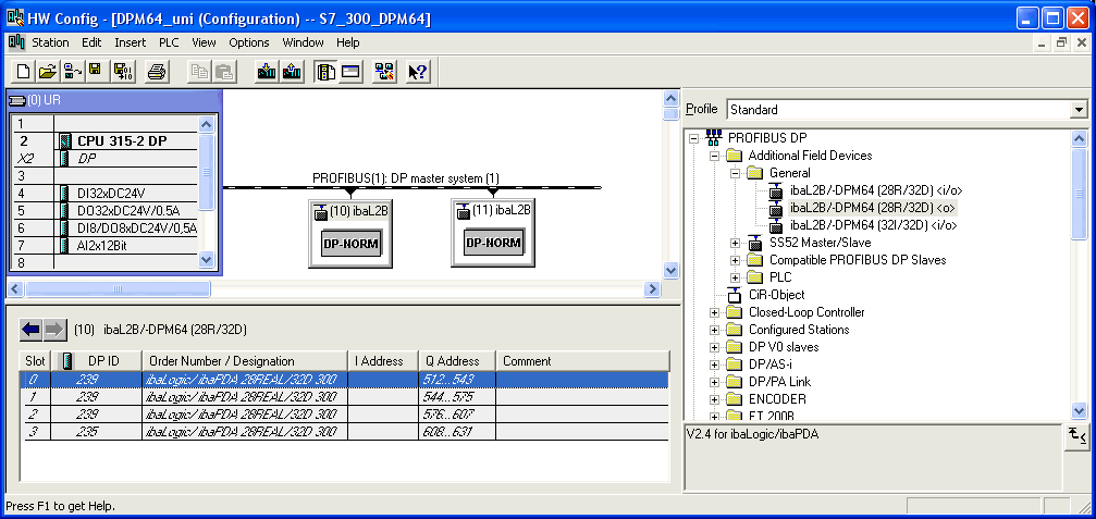
In your S7 program, you must set the peripheral output address in network 3 (LADDR parameter) to the DP output address in the hardware configuration (A address column).
Note
Do not forget to take into account the offset of the data set within the PROFIBUS telegram.
Example: To address the 1st analog value in mode "3", take into account an offset of 8 bytes/4 words.
For further information, see chapter Output data.
-
Now, download all modified blocks to PLC.


Step 5: ibaPDA setup and test
In step 1 you should have already defined one module ibaBM-DP-64 in the I/O Manager of ibaPDA.
-
In the signal tables of the module in ibaPDA, activate (check) the analog and digital channels of the modules and enter signal names and comments if required.
-
Start measurement by clicking on <GO>.
-
Drag & drop the signals from the signal tree into the signal view.
If all connections are done and if the S7 PLC sends data via the PROFIBUS then signal curves should appear in the trend graphs of the ibaPDA client. If the measurement curves are not immediately visible, right-click in the signal strip and select the Autoscale strip command in the context menu.