By means of the following instruction, you learn how to integrate ibaBM-DP step by step into ibaPDA and how to configure measurement signals. The description refers to the 32Mbit Flex mode, see chapters Device setting 32Mbit Flex mode and Data acquisition 32Mbit Flex.
Special features and deviations that must be taken into account in 32Mbit compatibility mode can be found in chapter Notes on the compatibility mode 32Mbit.
Note |
|
|---|---|
|
Make sure that 32Mbit Flex mode has been selected using the S1 and S2 rotary switches, see chapter Device setting 32Mbit Flex mode. The basic device settings like network settings, passwords etc. should be done in advance via the web interface. With ibaPDA, you can define the PROFIBUS slave addresses and configure analog and digital measurement signals. The following description refers to ibaPDA version 6.32.0 or higher. |
|
Preparation
-
Connect the device to a voltage source and switch on the device, see chapter Indicating elements.
-
Establish a FO connection between the TX connector of the device and a free RX input of an ibaFOB-D card as well as a FO connection between the RX connector and a free TX output of the ibaFOB-D card.
The TX/RX connectors of the ibaFOB-D card belong together in pairs, i. e. you cannot use just any free TX/RX connectors.
-
Dark gray fibre optic connections are receiving RX inputs.
-
Light gray FO connections are transmitting TX outputs.
-
-
Start the ibaPDA client
 .
. -
Open the I/O Manager
 .
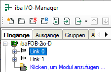
.On the left-hand side in the I/O Manager, the available system interfaces are displayed.
-
Choose the right ibaFOB-D card and mark the link, ibaBM-DP is connected to.
-
Click with the right mouse button on the link and select Autodetect.
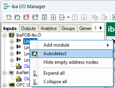
The device is identified automatically and displayed in the module tree. Depending on the Flex address (switch S2), the device appears at the respective address position 1-15. See also chapter Device setting 32Mbit Flex mode.
-
Optionally, you can also add the device manually. In this case select Add module – ibaBM-DP in the context menu.
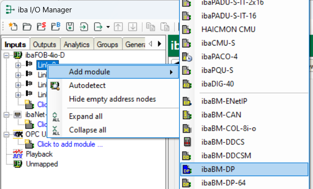
According to the selected Flex address (switch S2), the device has to be dragged to the correct address position using drag & drop. See also chapter Device setting 32Mbit Flex mode.
-
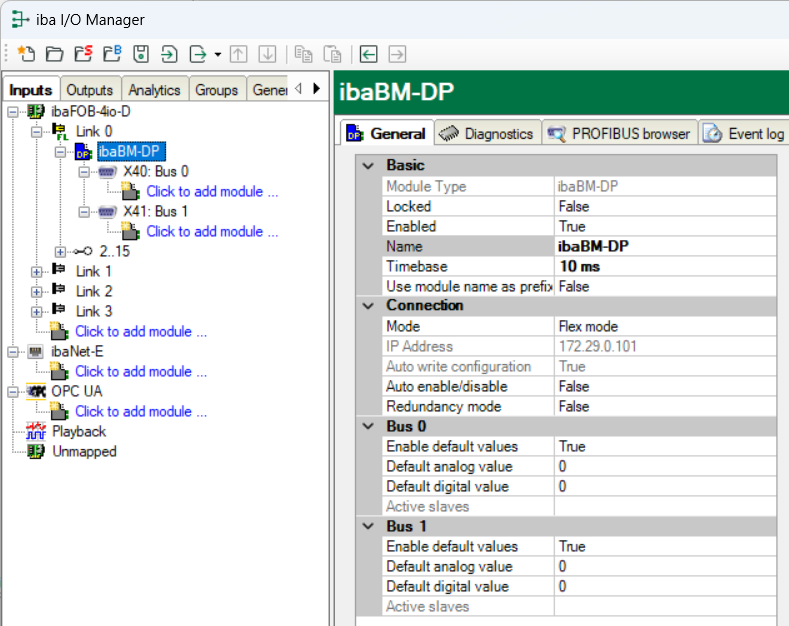
On the General tab define the parameters of ibaBM-DP.
The following parameters are important:
-
Name: Assign a meaningful name to the connected device.
-
Timebase: Set the time base with which the device data is to be acquired in ibaPDA.
-
-
Decide whether ibaBM-DP should work with active slaves and/or only as a sniffer.
If the device is to be connected with one or more active slaves to the PROFIBUS, you first have to configure the PROFIBUS on the PLC side for defining the slave numbers of the active slaves of the device, see chapter Operation as active slave.
Moreover, the PROFIBUS parameters of all participants are needed, you want to measure data from (slave no., length of inputs and outputs and data types). These are also needed for the pure sniffer operation.
-
Add a module under the “ibaBM-DP” device module. To do this, right-click on the “ibaBM-DP” device module and select in the desired module from the list via Add module from the context menu.
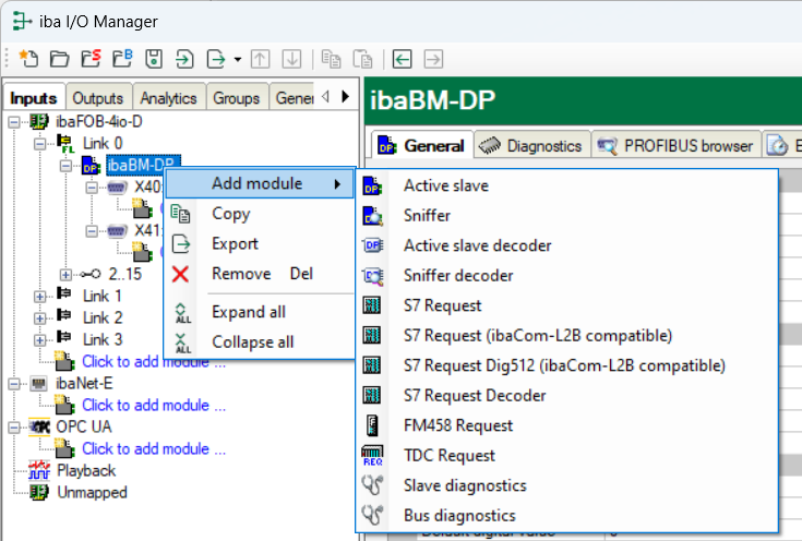
Optionally, for adding a module, you can also select the option "Click to add module…" marked in blue under the bus connection. Depending on the license, the following modules are available:
-
Active slave, Sniffer, Active slave decoder, Sniffer decoder, Slave diagnostics, Bus diagnostics
-
With additional ibaPDA license: S7 Request, S7 Request Decoder, FM458 Request, TDC Request.
For information regarding these modules, please read the respective manuals.
-


Configure active slave ("Active slave" module)
With this module, you create a single active slave on ibaBM-DP to which the master of the PROFIBUS line can send data directly.
-
Enter the address of the slave (as parametrized in the configuration of the PLC) on the General tab under Slave number.
-
Under Bus number you can enter the PROFIBUS line (0: connector X40, 1: X41) on which the active slave is operated.
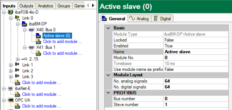
If you want to operate several active slaves, add more modules of the "Active slave" type.
For a detailed description of the "Active slave" module, please see chapter Active slave module.
-
On the General tab, enter the No. analog signals and the No. digital signals in the "Active slave“ module. The default setting is 64, a maximum of 512 analog and 512 digital signals can be assigned per module, a total over all modules of 1024 analog and 1024 digital signals. This value determines the length of the signal tables on the Analog and Digital tabs.
-
In the Analog tab, enter the signals you want to acquire in sequential order. Assign a name to each signal (Name column). In the I/O, Address and Data type column, define the information where the signal can be found in the interface of the slave.
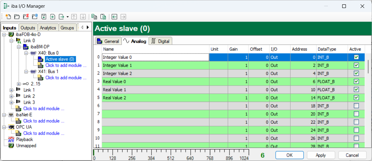
Note

By clicking on the header of a column, all the settings in the rows below are filled in automatically.
Examples:
-
You want to set a different data type beginning with a certain row: Change the data type in the first concerned row, and click on the Data type header. The data type will be changed automatically in all lines below.
-
If you want to have calculated the addresses automatically depending on the selected data type: Set the right address in the first row (usually 0) and then click on the Address header. Now, considering the selected data types, the addresses are filled in automatically in sequential order.
Similar functions are also available for the other columns.
Thus, the project effort can be reduced.
-
-
If required, select a scaling value of the signals in the columns Gain and Offset for converting them into physical units.
-
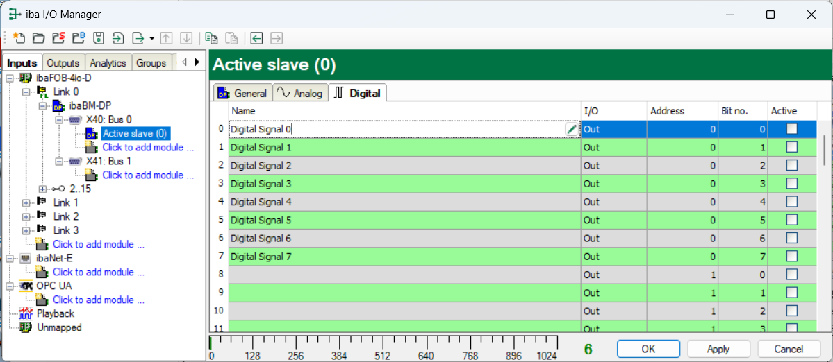
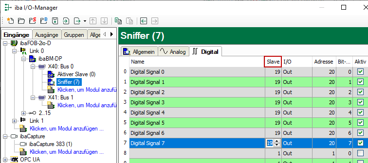
For the digital signals on the Digital tab, proceed as described above. A data type is not defined. The address offset is given in 1-Byte-steps. The individual signals are addressed via the bit numbers 0 to 7.


Sniffing on the PROFIBUS ("Sniffer” module)
With this module, you generate a sniffer on the bus that is able to record the existing telegram traffic between master and slaves within a PROFIBUS system.

For a detailed description of the "Sniffer" module, please see chapter Sniffer module.
-
Then enter the No. analog signals and the No. digital signals in the General tab. The default setting is 64, a maximum of 512 analog and 512 digital signals can be assigned per module, in total over all modules of 1024 analog and 1024 digital signals. This value determines the length of the signal tables on the Analog and Digital tabs.
-
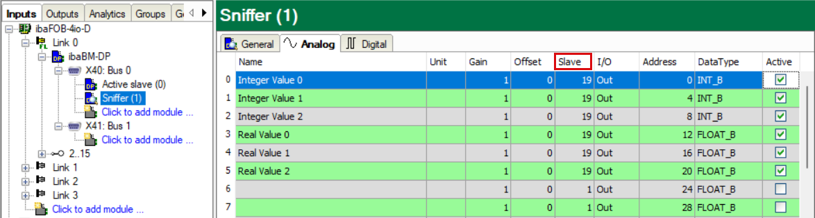
The signals on the Analog and Digital tab are configured as for the "Active slave" module. In the Slave column, enter the slave number the data is to be captured from.
-
If required, select a scaling value of the signals in the columns Gain and Offset for converting them into physical units. For sniffing, in general a scaling is needed, as the data is transferred in a normalized way over the PROFIBUS to the slave.
For example for a SIMATIC ET200 AO module, a +/- 10 V signal is transferred with the value range -27648 … 27648 (equals -10 V … +10 V). You find the physical meaning in the control program.
-
If a larger amount of digital signals has to be acquired, (e. g. status/control words of a large number of drives) the modules "Sniffer decoder" and "Active slave decoders" are a good solution. For a detailed description, please see chapters Sniffer decoder module and Active slave decoder module.


Complete and validate configuration
-
When all signals have been configured, activate the configuration by clicking on <OK> or <Apply>.
In course of the following validation, the configuration is transferred to ibaBM-DP. <OK> closes the I/O Manager, provided that no warning or error messages have appeared during the validation process.
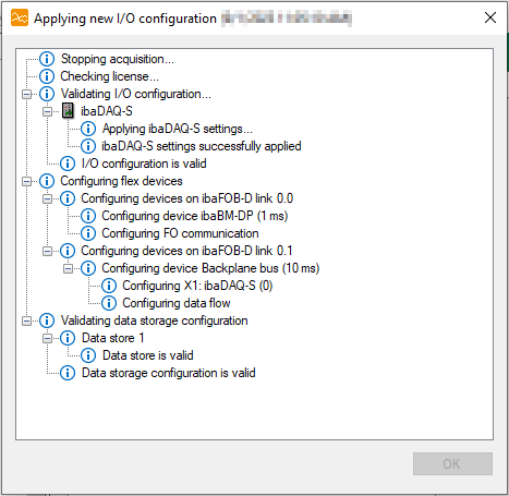
Of course, you can do the configuration step by step and hence check the validity of the current configuration.
-
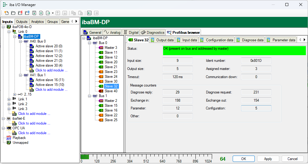
ibaBM-DP provides a wide variety of diagnostic features for PROFIBUS systems. The Diagnostics tab in the device module is very helpful. On this tab, the identified masters and slaves and their status are shown for both PROFIBUS systems.
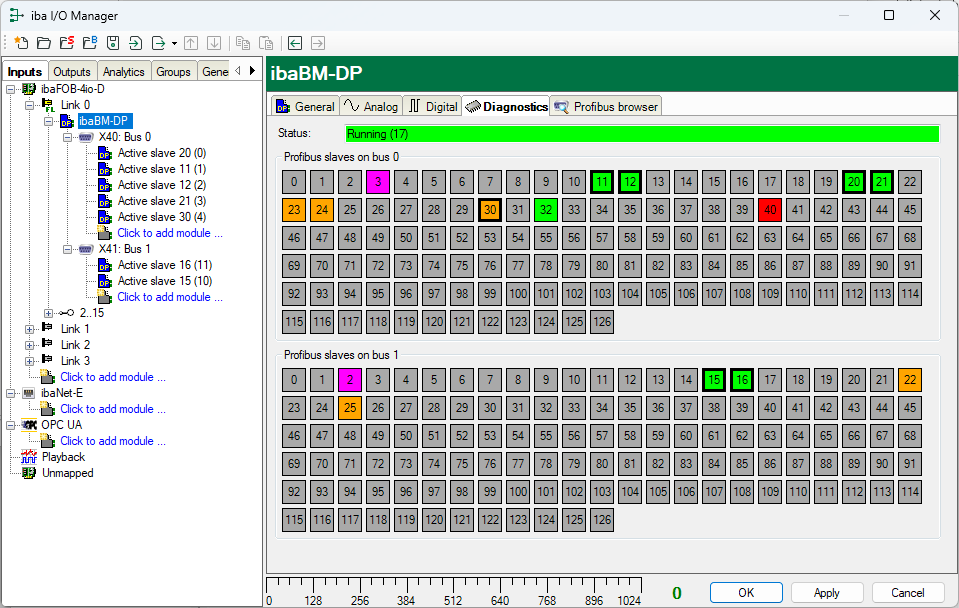
The Profibus browser tab shows detailed information about both PROFIBUS systems (e. g. bus cycle time) and about the input and output areas of each slave.
For detailed information on the diagnostic functions, see chapter Slave diagnostics module.


