A temperature signal is to be transmitted from an S7 PLC to an ibaLogic system. A generator signal is to be sent from ibaLogic to the S7.

Step 1: FO connecting and cabling
Because the data are to be transmitted in two directions, the bidirectional modes 8, 9 and B are available.
-
Take a duplex fiber optic cable and connect the transmitting link (TX) on ibaBM-DP with a receiving link of der ibaFOB-io or ibaFOB-4i card of the ibaLogic system.
-
Use the 2nd wire to connect the input (receiver, RX) on ibaBM-DP to an output of the ibaFOB-io or ibaFOB-4o card.
Step 2: GSD installation and hardware configuration
-
Start the “HW Config” tool in the current S7 project and install the GSD file with name ibaF08n3.gsd
For further information, see chapter Operating modes overview.
-
In the web interface of ibaBM-DP set the operating mode to mode “8”.
-
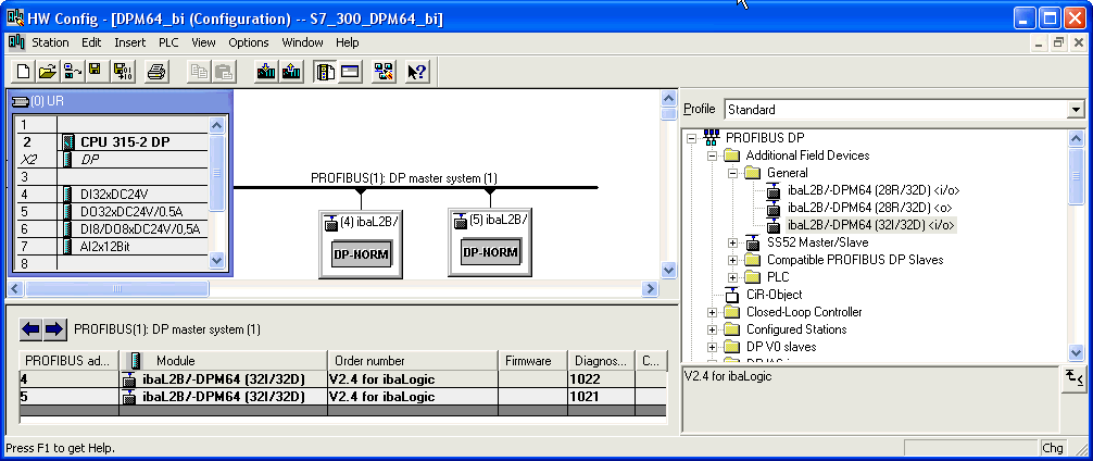
Open the “PROFIBUS DP” folder in the hardware catalog of "HW Config".
-
Connect an DPM64 module with the PROFIBUS line by drag & drop and set a DP address for this module (in this example 4).
Note

The same address has to be set in the web interface on ibaBM-DP.
-
If you want to use both slaves on ibaBM-DP connect another module with the PROFIBUS line and assign in HW Config the other DP address set in the web interface.

Step 3: Establishing a connection to the DP
-
Connect the left DP interface on ibaBM-DP with the DP interface of your S7-PLC.
-
If ibaBM-DP is the last device on the DP line, then also activate the terminating resistor in the PROFIBUS connector.
-
Download the system data to the S7-PLC with HW Config and start the PLC.
As soon as the connection between the DP master and the ibaBM-DP slaves has been established the “Bus“ LED should light yellow and the “Active” LED white.
Step 4: S7 test program
-
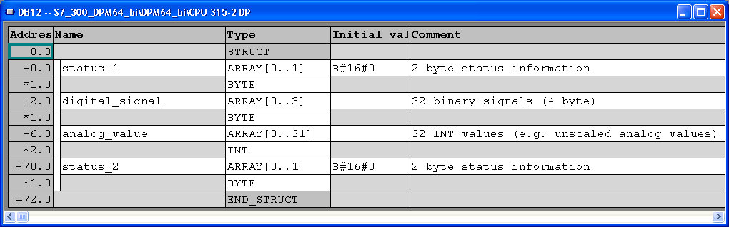
Generate a SEND-DB12 (or any free DB number) in your S7 project.
-
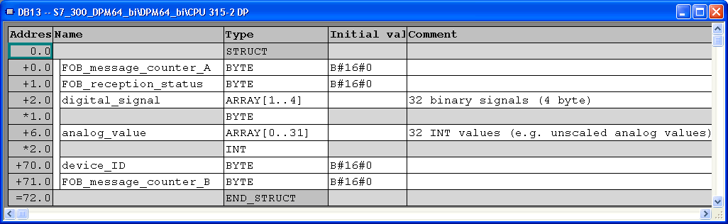
Generate a RECEIVE-DB13 (or any free DB number) in your S7 project.
-
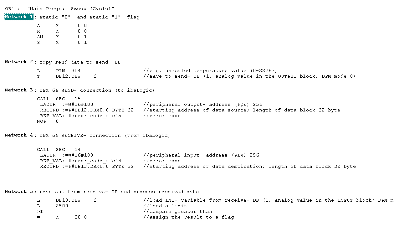
Enter the content of OB1. Define the local variables and call SFC14 (DP receive) and SFC15 (DP send), both blocks from the S7 standard library, in OB1. Other FCs are also possible.
The unscaled temperature (0 to 32767) is stored as an INT value in DB12.DBW6 (in the 1st memory area for analog signals) and is passed on from there to ibaLogic.
Example for transfer of 32 bytes transmitting (DB12, SFC15) and receiving data (DB13, SFC14) in S7-PLC
-
In your program you have to adjust the peripheral input/output address in network 3 and 4 (LADDR- parameter) with the DP input/output addresses in the HW-configuration (column I-/ Q- Address).
Note
Do not forget to take into account the offset of the data set within the PROFIBUS telegram.
Example: To address the first analog value in mode 8, please consider an offset of 6 Bytes / 3 Words.
For further information, see chapter Operating modes overview.
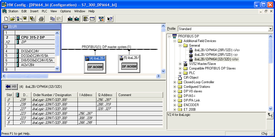
In this example the addresses PIW 256 and PQW 256 are displayed in HW Config. For S7-300, 3 ranges (2 with 32 bytes and 1 with 8 bytes) are automatically created per slave. The maximum size of transfer data with SFC14 and SFC15 to any DP device is limited to 32 bytes (only for S7-300). That means, if you want to transfer the complete block of 72 bytes, you have to call up the DP-SFCs three times in your S7 program.
-
Now, download all modified blocks to PLC.


Step 5: ibaLogic test program
-
Start ibaLogic and create a new test layout. Activate the ibaFOB-i/o or ibaFOB4i card in the system settings.
-
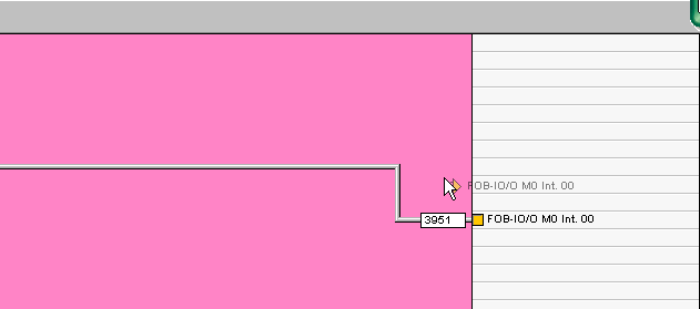
Data received from S7:
o be able to display the received data (temperature values) from the S7, the 1st INT analog value from the FOB_F/FOB-IO input resources must be used.
-
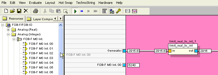
Transmit data to S7:
To create a signal in ibaLogic, you can use the generator (input resource).
To transfer the data from the ibaLogic system to the S7, the 1st INT analog output must be used for the FOB-F/FOB-IO output resources.
-
Start the SIMATIC-Manager and enter a new variable table. Display the transmitted generator signal (DB13.DBW6) in INT format

