Depending on the analog value type to be processed. integer or real, mode 8, 9 or B has to be set on the ibaBM-DP device for bidirectional operation. The notes for configuration of outputs in ibaPDA (from step 4) apply also, if the modes 5, 6 or 7 are used to transfer data from ibaPDA to a master.
For further information, please see chapter Settings.
-
Configure an applicable GSD file in the PROFIBUS configuration of the master.
-
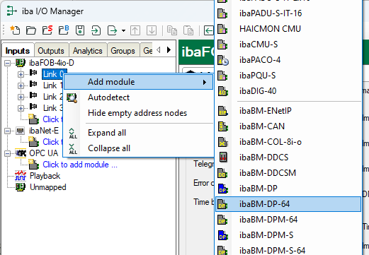
Add a module "ibaBM-DP-64" to the link of the corresponding ibaFOB card in ibaPDA I/O Manager.
-
Set the “DP-64 slave mode” in the General tab.
Note

The mode set on the device via the web interface must match the mode set ibaPDA.
Device mode
DP-64 slave mode (ibaPDA I/O Manager)
8
0 (2 x 32 integer)
9
1 (2 x 32 float)
B
3 (2 x 28 float)
-
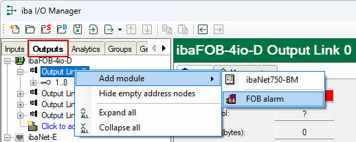
Add an "FOB alarm" module to the corresponding output link in the Outputs area of the I/O Manager.
-
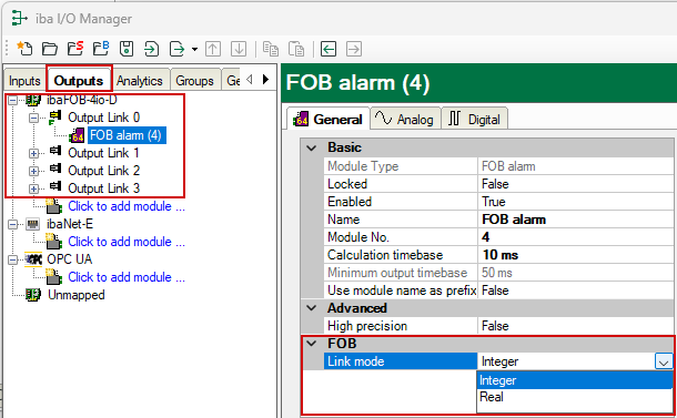
In the General tab of this module, set the "Link mode" to the correct data format "Integer" or "Real".
Device mode
Link mode
8
Integer
9
Real
B
Real
-
Enter the data to be written in the Analog and Digital tables.


