The so-called configured markers can either be anchored at certain positions on the base axis with fixed values or moved dynamically along the base axis by means of analog signals.
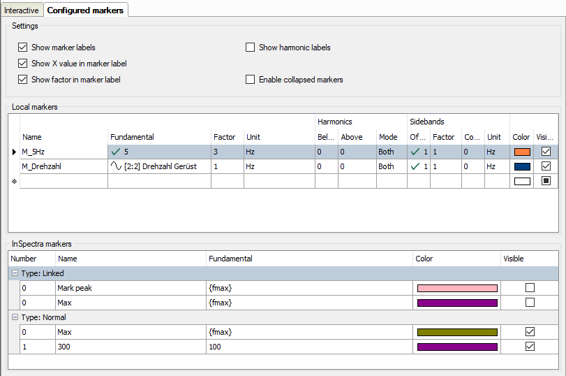
The markers must first be defined and configured. You can configure the markers in the Properties dialog of the FFT view, in the “Marker” branch.
Settings
Here you define whether a marker label is displayed and which information is to be displayed additionally: Value on the X-axis and/or factor.
To create a marker, you simply have to enter the required information in the table line. As soon as you click in the empty space below, a new, empty line is added.
Name
Enter a clear name to be able to easily identify the marker. The name is shown in the display later on, too.
The entries for fundamental frequency, factor and unit determine the position of the marker on the base axis. The marker position is calculated by multiplying these three parameters.
Fundamental
You can enter a fixed value or select a signal for the fundamental oscillation or fundamental frequency. To select a signal, click in the table line and then on the arrow symbol. Select the signal from the signal tree.
If you want to use a signal for controlling the marker position, select a signal complying with the frequency you want to monitor.
In the example of the above image, we have selected a velocity, more precisely the speed of a drive in rpm, to control the marker. In doing so, frequencies of interest can be easily tracked, e. g. during the acceleration and braking phase of a machine. This is especially easy to see in the main window’s waterfall and contour view.
Note |
|
|---|---|
|
If the signal for the fundamental frequency is negative, the marker is not displayed. |
|
Factor
The default value of the factor is 1. You can enter another factor if, for example, the marker is to be positioned at a multiple or a fractional part of the fundamental frequency.
If the position of the configured marker in the display is changed by dragging, the factor is updated.
Note |
|
|---|---|
|
The Add speed marker function in the FFT display automatically generates a configured marker for the speed signal. The speed signal is configured in the InSpectra Expert or InSpectra Auto-Adapting module. |
|
Unit
As to the unit, you can choose between Hertz (Hz) and revolutions per minute (rpm). Depending on the settings, another, internal factor is taken into consideration:
-
Hz: Factor = 1
-
rpm: Factor = 1/60
Order can also be selected for order spectra.
Harmonics
As with the interactive marker, you can individually determine the number of harmonic markers above or below the marker frequency for every static marker. Additionally, this mode allows you to select whether only the even or odd harmonic components are taken into consideration or both types.
Sidebands
As with the interactive marker, you can individually determine the number of sideband markers and the sideband offset for every marker, static and depending an a signal value. If you drag the sideband markers, the factor is updated during dragging.
Sidebands can have a different unit than the marker itself. You can select the unit here.
Note |
|
|---|---|
|
If the sideband offset is specified by a signal, the value of this signal always has to be >=0. If the value is negative, the offset = 0 and no sideband markers are displayed. |
|
Color
Here, you can allocate an individual color to every static marker
Visible
This option decides whether a fixed marker is displayed or not. This is the only possibility of enabling or disabling static markers for the display. The marker button in the toolbar of the FFT view does not control the static markers!
“Enable collapsed markers" option
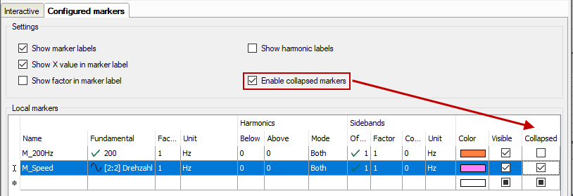
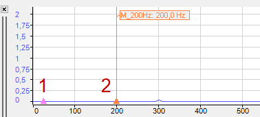
When you enable this option, an additional column appears in the marker table, in which you can decide for each marker whether it is normal, i.e. it should be displayed as a line and possibly with a label, or only as a triangle based on a spectrum.
The example above shows a collapsed marker (1) and a normal marker (2).
InSpectra marker
The InSpectra markers are shown in the table below.
The settings of the InSpectra markers can only be changed in the InSpectra profile. Only the visibility can be set here.


