Though being very detailed and specialized, some of the information under the Info tab may also be useful for the average user.
Displayed properties and parameters vary depending on the operation mode the link is running in.
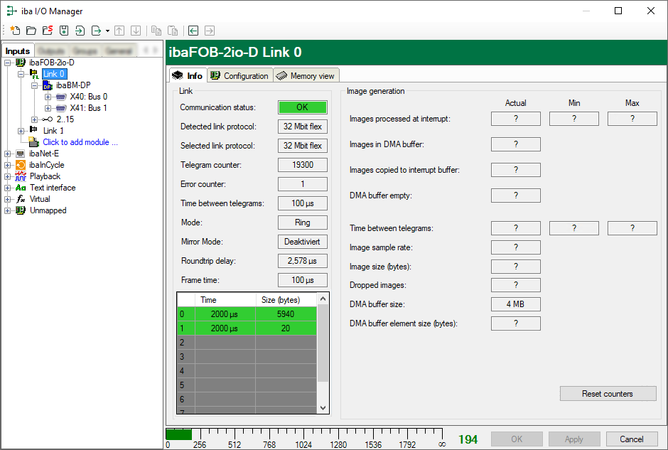
Permanent information in the Link area
Communication status
OK if the FO communication works. This means that the messages received correspond with the mode that is configured on the link. The connection mode is determined by the module connected to the link, for example if the connection mode is set to 3.3 Mbit, a ibaPADU-8 module is set up. If an ibaPADU-8-ICP module is configured, the link will be set to 5.0 Mbit/s mode.
Detected link protocol
This is the link protocol detected by the card. This can either be 2.0 Mbit/s, 3.3 Mbit/s, 5.0 Mbit/s, 32 Mbit/s or "?" (no connected device).
Selected link protocol
This is the link protocol in which the connection is configured. It is determined by the module connected to the link.
Telegram counter
Counter of messages correctly received.
Error counter
Counter of received messages containing errors (e.g. incorrect checksum) If this counter is changing, this means the FO communication is not working correctly.
Time between telegrams
The time span between the two latest correctly received messages.
Additionally available in the Link area when running in 3.3/2.0 Mbit/s mode
FO signal strength
This is the difference between the maximum value and the minimum value received from the FO unit. The maximum value is 255. The higher this value, the stronger the FO input signal.
Device ID
This is the device ID of the last device in the FO chain, attached to the link.
Telegram format
This is the format of the analog data transferred in the telegram. The possible values are integer, real and S5 real.
Additionally available in the Link area when running in 5.0 Mbit/s mode
Status of the device firmware
Status of the firmware of the connected device.
Table gain (amplification) and filter
Gains and filters configured in the device. This applies only to the ibaPADU-8-ICP device.
"Image generation" area
The information on the right side of the dialog describes the image generation. An image is a collection of bytes that the board writes into the computer system memory via DMA. This image contains all the data of the measurement signals from that link.
Here is a short description of the image generation information:
Images processed at interrupt
These counters show how many images were available in the DMA buffer when the last interrupt occurred. This value should normally correspond with the interrupt time divided by the image sampling rate.
Images in the DMA buffer
This is the number of images that are in the DMA buffer. This number should remain constant. If this number starts increasing, an error occurred. This can be the case if e. g. an interrupt is missed.
Images copied to interrupt buffer
This counter shows how many images have been captured from the DMA buffer and processed by ibaPDA. This counter should increase constantly.
DMA buffer empty
This counter increments each time when the interrupt fires while the DMA buffer is empty. If this is the case, the driver will use the value 0 (zero) for all signals that are on this link. This happens if the FO connection is interrupted.
Time between telegrams
The time between the last two messages received correctly This corresponds to the time in the FO communication information; however, the driver maintains the minimum and maximum values. There should not be much difference between the minimum and maximum values.
Image sample rate
The rate at which the board writes images to the DMA buffer. This should be at least equal to or faster than the fastest time base of the modules connected to this link.
Image size
The image size given in bytes. Multiplying the image size by the image recording rate gives the number of bytes/sec transferred through this link over the PCI bus.
Dropped images
This counter increments when the card’s DMA FIFO is full and additional images are added. If this is the case, a severe error occurred. This means that the card cannot transfer any images via the PCI bus.
DMA buffer size
Size of the DMA buffer for this interface
DMA buffer element size
Size of the elements in the DMA buffer (in bytes)
Available in 32Mbit Flex mode
By using the 32Mbit Flex mode protocol you can connect up to 15 devices in a ring topology. The link numbers 1 to 15 in the signal tree below the ibaFOB-D board correspond to the address, which is set on the rotary switch of the connected device.
Additional information is available as follows:
In the link area
Mode
Status of the connection mode:
-
-
Ring: one or more devices (cascade) are bidirectionally connected and the FO ring is closed.
-
Open chain: Only the fiber optic input is connected to a device. The output is not connected or the FO ring is interrupted
-
Time between telegrams
Time between two telegrams measured by the ibaFOB-D board. It should be equal to the configured frame time.
Mirror mode
Indication whether the mirror mode is enabled or not.
In mirror mode multiple ibaPDA systems can receive the data from the same 32Mbit Flex-devices at the same time.
For detailed information on the mirror mode, refer to the manual of the card.
Roundtrip delay
Telegram cycle in the closed FO ring. The time depends on the number of the connected devices in the ring (approx. 2 µs per device).
Due to the roundtrip delay the data of the connected devices might be captured asynchronously (up to one telegram cycle).
Frame time
Fixed cycle time the data frames are being sent. (Smallest set time base of the connected devices or 100 µs, if this time base is an integer multiple of 100 µs). The time base of all devices must be a multiple of the smallest time base.)
Table
The table shows the cycle time and the data size of the respective channel:
-
-
Row 0: Ethernet channel
-
Rows 1-15: connected devices with the respective address 1-15
-