Description
ibaPDA-Interface-PC Link is a software interface for data acquisition on a DCS network as used by Reliance Automax PC Link.
Provided there is a DCS network card inserted in the ibaPDA PC, the ibaPDA software enables the measuring of data sent over the DCS network.
The main properties of the software interface are:
-
Automatic detection of the DCS network interface card installed
-
Up to 4 cards are supported per PC.
-
Up to 1024 PC Link modules can be configured.
-
3 different module types for data acquisition
-
The "Asynchronous" mode is supported on the PC Link module.
-
Both the "Active" and "Passive" mode are supported.
-
Signal browser
A Reliance Automax DCS Network consists of up to 56 drops or nodes. Each drop has 64K 16bit registers. Drop 0 functions as master and contains information on the network, such as which drops are active, broadcast data, etc. PC Link provides a connection to a DCS Network for an IBM AT compatible standard computer.
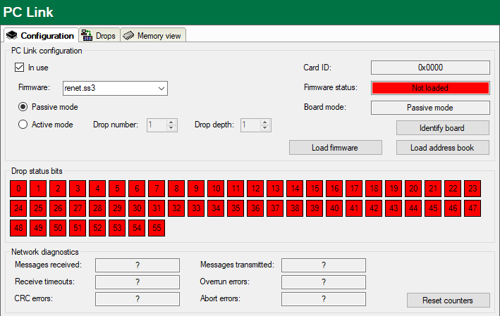
Interface configuration (Configuration tab)
"In use"
Check this option if you wish this interface to be used.
Firmware
Firmware file to be selected and loaded. The PC Link interface card can run as a master
or a slave (drop), depending on the firmware file loaded. The firmware files should
be located in the program path of the ibaPDA server. If this is not the case then it should be installed using the CD ROM from
the card’s manufacturer (SST). The file can then be found under SST\…\Reliance\Modules.
-
For slave mode (drop), select
renet.ss3from the list. -
For master mode, select
renetm.ss3.
Passive mode
This mode is available if the PC Link interface card runs as slave (drop). If the Passive mode is enabled, ibaPDA is not "visible" on the bus to other connections or masters. The bus is only monitored.
Active mode
This mode is available if the PC Link interface card runs as master or slave (drop). If Active mode is enabled, multiple drops can be mapped on the PC Link board. These drops are then "visible" on the bus for other participants and can be addressed for message transmission.
-
Drop number and drop depth Enter the number of the first drop to which a PC Link card is allocated here. Enter the total number of drops according to the number of the following drops, starting with the previously entered Drop number.
<Identify board>
By click on this button, you can identify and initialize the card.
<Load firmware>
This button allows you to load the selected firmware file on the card.
<Load address book>
Clicking this button, allows you to load the address book of the DCS network. This
will open a file browser where you can select the correct database file. By default,
this file is called $NET.dbf. The address book is required for PC Link symbolic modules when using the DCS symbol
browser.
Drop status bits
There is a status indicator in this area for each drop in a DCS network.
When clicking on a drop’s status field, the display will switch to the Drops tab, showing the 64 values of the corresponding drop.
Drop diagnostics (Drops tab)
On this tab you’ll find the contents of the 64 values of each drop. Enter the drop number in the input field in the upper left corner and choose between "Decimal" and "Binary" display mode.
A status indicator in the upper right corner shows the drop status.
Available modules
-
PC Link; 0 to 1000 analog signals and 0 to 1000 digital signals (default 32/32)
-
PC Link Dig512; up to 512 digital signals, in 32 groups of 16 signals each
-
PC Link Symbolic; 0 to 1000 analog signals and 0 to 1000 digital signals (default 32/32), featuring a DCS symbol browser for easier signal selection, based on the DCS address book.
For further information on module configuration see:
Product name
ibaPDA-Interface-PCLink-Automax
Other documentation |
|
|---|---|
|
For a detailed description of this interface and its configuration, please refer to the corresponding manual of the product ibaPDA-Interface-PCLink-Automax. |
|