To add a profile for a lookup table, click the blue Configure profiles link in the General tab at the bottom of the lookup table module.
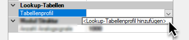
Alternatively, you can open the drop-down list in the Table profile row and click on <Add lookup table profile>.
In both cases, the Lookup tables dialog opens. In the second variant, a profile is created immediately.
Below the left window of the dialog you will find a set of buttons with the following functions:
|
|
Add profile |
|
|
Copy selected profile |
|
|
Delete selected profile |
|
|
Import profile(s) from a *.lookupTableProfile file |
|
|
Export selected profile to a *.lookupTableProfile file |
Add a profile and name it so that the function or table content is recognizable.
Select whether the key (contents of the left table column) has a numeric data type or is a text signal. This type usually corresponds to the data type of the signal that transmits the key value and is later configured as a key selector signal.
If the set type and key do not match, an error message is displayed.

Enter another value that will be output if no matching key is found in the table, e.g., "Key unknown".
Now populate the table. You can either enter the data pairs (key-value pairs) manually in each row or copy a ready-made table, e.g., from Excel, to the clipboard and paste it from the clipboard.
To do this, use the button ![]() on the right edge of the dialog.
on the right edge of the dialog.
Note |
|
|---|---|
|
Make sure that the keys are always unique. If there are two or more identical keys in the table, only the result value of the first of these keys is output. |
|
The buttons at the edge have the following functions:
|
|
Move selected rows up |
|
|
Move selected rows down |
|
|
Delete selected rows |
|
|
Copy all rows |
|
|
Paste from clipboard, starting from the selected row |
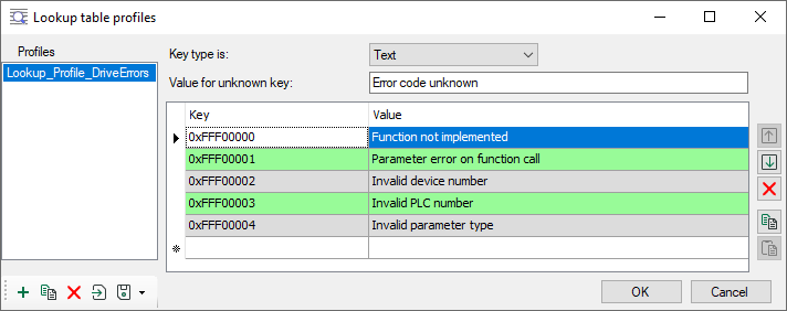
Example
The following figure shows a profile with five error messages from drives. The error codes (keys) and values are entered as text.
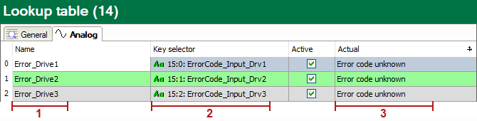
This lookup table is used for 3 drives. Therefore, the lookup table module is configured for 3 analog signals.
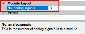
The 3 output signals of the module (1), key signals (2) and current values (3) are displayed in the module’s Analog tab.
In the example, the key signals were implemented with ibaQPanel text inputs for the purpose of easier explanation. In a real application, these can of course be signals from a PLC or other systems that transmit the error code.
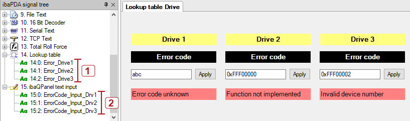
After completing the module configuration and restarting the acquisition, the analog signals from the lookup table module are available in the signal tree (1) and can be displayed and recorded. In this example, they were placed on labels in a QPanel (bottom row).
The error code (= key) is entered manually here. If, as with drive 1, a key is entered that is not in the table (profile), then the default text (value for unknown key) appears.
If correct keys are entered, then the appropriate error texts appear in the red fields.