Name
Here, enter a clear text name of the signal.
It is recommended to use an project specific nomenclature for a better transparency and comprehension, particularly when many signals are used. The name for the signal can be chosen after its technological function or the installation site in the plant.
The number of characters is unlimited. The signal names are stored in the data file and indicated in ibaAnalyzer.
Comment 1 and Comment 2
Each signal can be assigned up to 2 comments. Comments can be used to provide additional information about a signal. This could be an extended signal description or information in another language. The comments can be entered in the signal tables in different ways:
-
Enter the comment directly in the cell if the comment column is visible.
-
In the cell of the signal name, click the
 button and enter the comment in the comment field. Then click <OK>.
 -
When using Request modules for selected PLC systems, the comments are loaded together with the signals if comments are supported by the PLC system.
Tip |
|
|---|---|
|
Comments are of great use because:
|
|
Visual min. and visual max. (analog signals only)
These settings can be used to limit the Y scale of a trend graph to a minimum and a maximum value. These settings only apply to the trend graph if the corresponding Y-axis property "Visual scale configured on signal" is enabled.
This helps to determine the Y scale already in the configuration phase provided the final signal range is known.
Moreover, the Y-axis automatically adjusts the Visual min. and Visual max. values as soon as you open a trend graph with such a signal. For doing so, you have to set the "Visual scale configured on signal" property of the Y-axis in the trend graph's preferences. The Y scale immediately shows the expected range.
Min and Max (analog signals on ibaPADU modules and other A/D converting modules only)
Lower and upper limit of measuring range given in physical units.
Preset values are -10/+10 for the standard modules ibaPADU and -20/+20 for ibaPADU-8-I modules. This corresponds to the voltage range of real devices of -10 V to +10 V or from -20 mA to +20 mA.
If you do not want to measure exactly the same range, but other physical quantities like temperature, pressure, speed etc., you should enter the minimum and maximum value corresponding to the limits of the measurement range of the device in physical units.
The value can be entered directly or with the help of the two-point-scaling dialog.
Value range: -32768 to +32767 (Integer)
Example
A temperature measurement connected to an ibaPADU-8 module delivers the values -10 V at -10 °C and 10 V at 43 °C. In that case, you should enter -10 (min.) and 43 (max.).
The analog voltage level of -10 V is assigned to the temperature -10 °C.
The analog voltage level of +10 V is assigned to the temperature 43 °C.
Tip |
|
|---|---|
|
By entering these values, you do not set real limits to the measurement, but rather a linear scaling rule. If you do not know the actual limits of a measurement device, just take two values you know for sure, e. g. from a calibration or test measurement, and use the two-point-scaling dialog. |
|
Two-point-scaling dialog
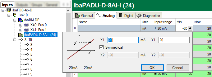
The two-point-scaling dialog can be used to provide a scaling factor for analog signals by entering 2 points (X1/Y1 and X2/Y2) of a straight line. This dialog helps to scale the physical input quantity (e.g. voltage on ibaPADU-8) in order to get a value in physical units of the measured quantity (e. g. pressure, speed, temperature, etc.)
You can open the dialog for two-point scaling with a click on the ![]() button the fields "Min", "Max", "Gain" or "Offset". (Cursor must be positioned in
the field for the button to appear.)
button the fields "Min", "Max", "Gain" or "Offset". (Cursor must be positioned in
the field for the button to appear.)
If you know that one of the values is 0/0, you can check the "Symmetrical" check box and enter only one value. (X1/Y1).
If the connected module has a physical input range, this range is shown in the dialog (e.g. from -10 V to +10 V).
Unit (analog signals only)
Assignment of an engineering unit (such as Ampere, Volt, m/s, tons etc.) for the signal. This entry can be up to 11 characters long and is regarded as a comment field only. It is always displayed in conjunction with a numerical display of the values.
Gain and Offset (analog signals only)
The values for gain and offset describe a linear characteristic curve for scaling. If incoming values are given in physical units, gain and offset can be ignored, i.e. set gain = 1 and offset = 0.
However, control and regulation applications of the connected automation systems often use normalized values so that analog signals vary, e.g., only between 0.0 and 1.0 or -1.0 and +1.0. In order to get a correct scale for display in terms of physical units, a scaling factor needs to be specified. This factor is determined from the gain and offset parameters.
Gain and offset can be entered directly or set by means of the two-point scaling with two pairs of applicable values.
You can open the dialog for two-point scaling with a click on the ![]() button in the fields "Gain" or "Offset." (Cursor must be positioned in the field
for the button to appear.)
button in the fields "Gain" or "Offset." (Cursor must be positioned in the field
for the button to appear.)
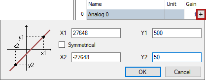
Example
With a SIMATIC ET200 AI/AO component, a ±10 V signal is transmitted with the value range -27648 to 27648 (corresponding to -10 V to +10 V). The transmitted value has a physical meaning in the control program (e.g., temperature 50 °C up to 500 °C). A conversion can be set via Gain/Offset so that the unitless value captured is recorded converted into the physical unit.
In order to facilitate the gain/offset calculation, by clicking on the coordinate cross a help dialog box appears in the Gain or Offset field in which you simply specify two bases of the linear equation. The gain and offset are then calculated automatically.
Active
Activation of signals
A click on the "Active" column heading enables (check mark) or disables (no check mark) all the signals for the measurement at the same time. Individual signals can be enabled in the signal-specific selection box. No acquisition takes place for disabled channels, so that such channels are available neither for visualization nor for storage.
Furthermore, disabled signals are not taken into account in the signal statistics (signal usage display).
Entries – such as names or physical units – remain unchanged. They are available again right after reactivation of a signal.
Actual value
The fields in this column show the actual value of the signals. Even if the data acquisition is not running yet, the actual values may be displayed, as they are directly read from the hardware driver. As for the value display, you can choose between scaled and raw values. Click on the column header to toggle the values. If scaled values are on display, the header shows a little icon:

Alternatively, you can use the context menu anywhere in the signal table to enable/disable scaled values display.
In some cases, "NaN" (= Not a Number) instead of a number can be displayed. This can happen with a few modules if no valid value is available (e.g. ibaPACO-4).
For digital signals, only the values 0 and 1 are permitted.
Address
The Address column is mainly available in modules which communicate over network interface, Xplorer interface or other bus systems.
The address determines where the signal in question is located within the net data range of a telegram or Dual-Port RAM (given in bytes). For some modules the address value can be displayed as decimal or hexadecimal value. The signal to be measured is always identified by the combination of address and data type (in the adjacent column). If you enter the data types first, you can let the system determine automatically the addresses by a double-click on the column header. This is useful if signals of different data types are consecutively packed for transmission.
Data type/Bit no.
The interface type, respectively the module type determines which data types are supported. For analog signals the selection of these data types can be found in a drop-down list in the fields of the Data type column. The data type determines the address of the next signal.
For digital signals only the bit number, relative to the byte address, is given in the column aside to identify the digital signal.
Symbol/Operand
Notably, the modules of Xplorer or Request interfaces have a column Symbol and/or Operand instead of Address und Data type.
These interfaces are exactly adapted to the controls or PLC systems which supply the signals to be measured. Mostly the symbolic addressing of the signals to be measured is supported. Therefore, in a first step, an address book is generated in the configuration of the system.
Usually you can open a symbol browser in the Symbol column in order to select the desired signals. The symbol name is copied automatically to the Name column, but you can overwrite it with any clear name.