Diagnostic modules are available for most Ethernet based interfaces and Xplorer interfaces. Using a diagnostic module, information from the diagnostic displays (e.g. diagnostic tabs and connection tables of an interface) can be acquired as signals.
A diagnostic module is always assigned to a data acquisition module of the same interface and supplies its connection information. By using a diagnostic module, you can record and analyze the diagnostic information continuously in the ibaPDA system.
Diagnostic modules do not consume any license connections because they do not establish their own connection but refer to another module.
Example for the use of diagnostic modules:
-
A notification can be generated, whenever the error counter of a communication connection exceeds a certain value or the connection gets lost.
-
In case of a disturbance, the current response times in the telegram traffic may be documented in an incident report.
-
The connection status can be visualized in ibaQPanel.
-
You can forward diagnostic information via the SNMP server integrated in ibaPDA or via OPC DA/UA server to superordinate monitoring systems like network management tools.
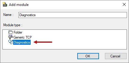
In case the diagnostic module is available for an interface, a "Diagnostics" module type is shown in the Add module dialog (example: Generic TCP).
Module settings diagnostic module
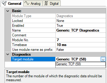
For a diagnostic module, you can make the following settings (example: Generic TCP):
The basic settings of a diagnostic module equal those of other modules.
There is only one setting which is specific for the diagnostic module: the target module.
By selecting the target module, you assign the diagnostic module to the module on which you want to acquire information about the connection. You can select the supported modules of this interface in the drop-down list of the setting. You can assign exactly one data acquisition module to each diagnostic module. When having selected a module, the available diagnostic signals are immediately added to the Analog and Digital tabs. It depends on the type of interface, which signals exactly are added. The following example lists the analog values of a diagnostic module for a Generic TCP module.
For example, the IP (v4) address of a Generic TCP module (see fig. above) will always be split into 4 parts derived from the dot-decimal notation, for better reading. Also other values are being determined, as there are port number, counters for telegrams and errors, data sizes and telegram cycle times. The following example lists the digital values of a diagnostic module for a Generic TCP module.
Diagnostic signals
Depending on the interface type, the following signals are available:
|
Signal name |
Description |
|---|---|
|
Active |
Only relevant for redundant connections. Active means that the connection is used to measure data, i.e. for redundant standby connections the value is 0. For normal/non-redundant connections, the value is always 1. |
|
Buffer file size (actual/avg/max) |
Size of the file for buffering statements |
|
Buffer memory size (actual/avg/max) |
Size of the memory used by buffered statements |
|
Buffered statements |
Number of unprocessed statements in the buffer |
|
Buffered statements lost |
Number of buffered but unprocessed and lost statements |
|
Connected |
Connection is established |
|
Connected (in) |
A valid data connection for the reception (in) is available |
|
Connected (out) |
A valid data connection for sending (out) is available |
|
Connecting |
Connection being established |
|
Connection attempts (in) |
Number of attempts to establish the receive connection (in) |
|
Connection attempts (out) |
Number of attempts to establish the send connection (out) |
|
Connection ID O->T |
ID of the connection for output data (from the target system to ibaPDA). Corresponds to the assembly instance number |
|
Connection ID T->O |
ID of the connection for input data (from ibaPDA to target system). Corresponds to the assembly instance number |
|
Connection phase (in) |
Status of the ibaNet-E data connection for reception (in) |
|
Connection phase (out) |
Status of the ibaNet-E data connection for sending (out) |
|
Connections established (in) |
Number of currently valid data connections for reception (in) |
|
Connections established (out) |
Number of currently valid data connections for sending (out) |
|
Data length |
Length of the data message in bytes |
|
Data length O->T |
Size of the output message in byte |
|
Data length T->O |
Size of the input message in byte |
|
Destination IP address (part 1-4) O->T |
4 octets of the IP address of the target system Output data (from target system to ibaPDA) |
|
Destination IP address (part 1-4) T->O |
4 octets of the IP address of the target system Input data (from ibaPDA to target system) |
|
Disconnects (in) |
Number of currently interrupted data connections for reception (in) |
|
Disconnects (out) |
Number of currently interrupted data connections for sending (out) |
|
Error counter |
Communication error counter |
|
Exchange ID |
ID of the data exchange |
|
Incomplete errors |
Number of incomplete messages |
|
Incorrect message type |
Number of received messages with wrong message type |
|
Input data length |
Length of data messages with input signals in bytes (ibaPDA receives) |
|
Invalid data points |
Number of received data points with missing configuration |
|
Invalid packet |
Invalid data packet detected |
|
IP address (part 1-4) |
4 octets of the IP address of the target system |
|
Keepalive counter |
Number of Keepalive messages received by the OPC UA Server |
|
Lost images |
Number of lost images (in) that were not received even after a retransmission |
|
Lost Profiles |
Number of incomplete/incorrect profiles |
|
Message counter |
Number of messages received |
|
Messages per cycle |
Number of messages in the cycle of the update time |
|
Messages received since configuration |
Number of received data telegrams (in) since start of acquisition |
|
Messages received since connection start |
Number of received data telegrams (in) since the start of the last connection setup. Reset with each connection loss. |
|
Messages sent since configuration |
Number of sent data telegrams (out) since start of acquisition |
|
Messages sent since connection start |
Number of sent data telegrams (out) since the start of the last connection setup. Reset with each connection loss. |
|
Multicast join error |
Number of multicast login errors |
|
Number of request commands |
Counter for request messages from ibaPDA to the PLC/CPU |
|
Output data length |
Length of the data messages with output signals in bytes (ibaPDA sends) |
|
Packet size (actual) |
Size of the currently received message |
|
Packet size (max) |
Size of the largest received message |
|
Ping time (actual) |
Response time for a ping telegram |
|
Port |
Port number for communication |
|
Producer ID (part 1-4) |
Producer ID as 4-byte unsigned integer |
|
Profile Count |
Number of completely recorded profiles |
|
Read counter |
Number of read accesses/data requests |
|
Receive counter |
Number of messages received |
|
Response time (actual/average/max/min) |
Response time is the time between measured value request from ibaPDA and response from the PLC or reception of the data. Actual: current value Average/max/min: static values of the update time since the last start of the acquisition or reset of the counters. |
|
Retransmission requests |
Number of data messages requested again if lost or delayed |
|
Rows (last) |
Number of resulting rows by the last SQL query (within the configured range of result rows) |
|
Rows (maximum) |
Maximum number of resulting rows by any SQL query since the last start of acquisition (possible maximum equals the configured number of result rows) |
|
Send counter |
Number of send messages |
|
Sequence errors |
Number of sequence errors |
|
Source IP address (part 1-4) O->T |
4 octets of the IP address of the target system Output data (from target system to ibaPDA) |
|
Source IP address (part 1-4) T->O |
4 octets of the IP address of the target system Input data (from ibaPDA to target system) |
|
Statements processed |
Number of executed statements since last start of acquisition |
|
Synchronization |
Device is synchronized for isochronous acquisition |
|
Time between data (actual/max/min) |
Time between two correctly received messages Actual: between the last two messages Max/min: statistical values since start of acquisition or reset of counters |
|
Time offset (actual) |
Measured time difference of synchronicity between ibaPDA and the ibaNet-E device |
|
Topics Defined |
Number of defined topics |
|
Topics Updated |
Number of updated topics |
|
Unknown sensor |
Number of unknown sensors |
|
Update time (actual/average/configured/max/min) |
Specifies the update time in which the data is to be retrieved from the PLC, the CPU or from the server (configured). Default is equal to the parameter "Timebase". During the measurement, the real actual update time can be higher than the set value if the PLC needs more time to transfer the data. How fast the data is really updated, you can check in the connection table. The minimum achievable update time is influenced by the number of signals. The more signals are acquired, the greater the update time becomes. Average/max/min: static values of the update time since the last start of the acquisition or reset of the counters. |
|
Write counter |
Number of successful write accesses |
|
Write lost counter |
Number of failed write accesses |


