The output module is not an autonomous module, but rather an extension of the MQTT module. With the output module, you can write data from ibaPDA to an MQTT-Broker.
Select the Outputs tab in the module tree to configure the module. You do not have to add it separately. The module will be available as soon as an MQTT module has been added.
The following module settings can be configured on the General tab:
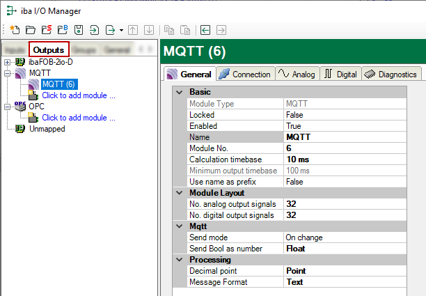
Basic settings
Module Type (information only)
Indicates the type of the current module.
Locked
A module can be locked in order to prevent change of module settings by accident or unauthorized users.
Enabled
Disabled modules are excluded from the signal acquisition.
Name
The plain text name should be entered here as the module designation.
Module No.
Internal reference number of the module. This number determines the order of the modules in the signal tree of ibaPDA client and ibaAnalyzer.
Calculation timebase
Timebase (in ms) for the calculation of the output values.
The calculation timebase and update timebase are NOT the same!
For interfaces whose modules have an input and an output side (same module number), the calculation timebase is identical to the module timebase on the input side. Hence, changing the calculation timebase also changes the module timebase on the input side and vice versa.
For interfaces with separate input and output modules (different module numbers), the calculation timebase can be changed independently.
The smallest possible calculation time base, i.e., the fastest possible update of the outputs, results from the smallest common multiple of all module time bases, and is at least 50 ms. .
This setting does not exist for the E-mail, OPC output and SQL command output modules.
Minimum output timebase (information only)
Smallest timebase for updating the outputs.
This value is calculated automatically by the system considering the current I/O configuration. It is displayed for information only. The minimum output timebase depends on the least common multiple of all module timebases, with a minimum of 50 ms.
Use name as prefix
Puts the module name in front of the signal names.
Module layout
No. of analog signals/ No. of digital signals
Determines the number of analog/digital output signals in this module. The default value is 32 for each. Maximum value is 1000.
Mqtt
Send Bool as number
Decide whether Boolean values in text mode should be written as FLOAT values (1 and 0) or as Boolean values (TRUE and FALSE).
Send mode
Determines when new data is written to the controller:
-
Cyclic: Data is written cyclically at the set update time.
-
On change: Data is written each time the signal data is changed.
-
On trigger: Data is written with every rising edge of the trigger signal.
All signals of a module are always written, regardless of the write mode.
Trigger signal
This field only appears when the "on trigger" send mode is selected. Select here a digital signal. A rising edge on this digital signal writes the signal values taken at the time of the rising edge.
Processing
Decimal point
Configure, which character should be used as decimal point.
Message format
Select if values in MQTT broker are stored in text format or as binary values.
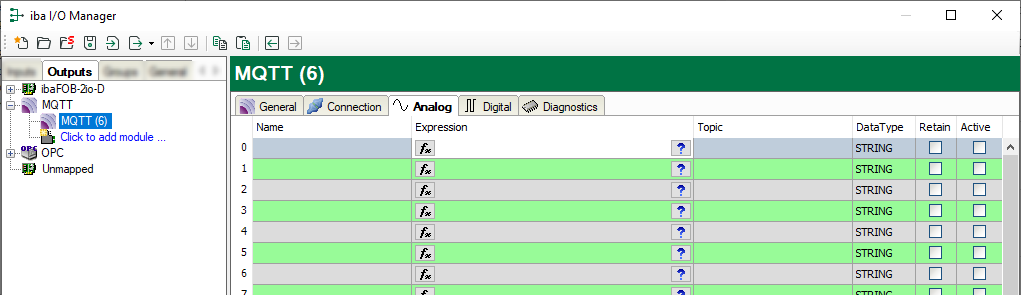
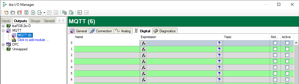
Output signals
The analog and digital signals be outputs, are configured in the expression editor. The expression editor can be opened by the <fx> button from each signal row.
In the Analog and Digital tabs enter a name for each signal and a data path to the broker. The following data types are supported for analog signals: SINT, BYTE, INT, WORD, DINT, DWORD, FLOAT, DOUBLE, STRING.
If you enable the Retain option, the signals are stored on the broker until they are overwritten.
Expression builder:
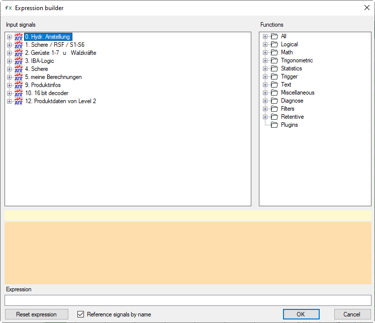
For more detailed information about the expression builder please refer to Expression builder (virtual signals)