The OPC UA client output module is also available with the license for the OPC UA client interface.
Other documentation |
|
|---|---|
|
Note the extensive explanations about the prerequisites and the connection setup in the manual about the product ibaPDA-Interface-OPC-UA-Client. |
|
Modules that have already been defined at the input level can also be seen in the tree of the output interfaces and can be used for output signals.
If you want to use the output signals, suitable writable tags must have been configured on the corresponding OPC UA server.
As with all output modules, the time base for the output cycle is at least 50 ms.
General module settings
The general module settings are partially identical to those on the input side and are retained.
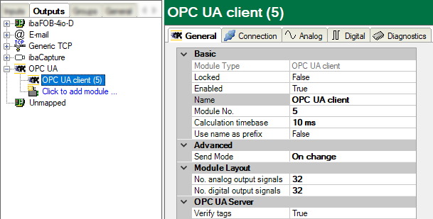
No settings with respect to the OPC server can be made for the output module.
In the Advanced section, you can use the Send mode to set when the output data should be written:
-
On change The output data is written when the signal values change, but not faster than the general output cycle time of the system allows (at least 50 ms).
-
On trigger The output data is written on each rising edge of the selected trigger signal (write trigger), but not faster than the general output cycle time of the system allows (at least 50 ms).
The number of analog and digital output signals is preset to 32. If necessary, you can change the number (max. 1000).
Clicking on <Select symbols> opens the OPC UA symbol browser. The prerequisite here is that the right address book of the OPC UA server was created. See all available tags here. By double-clicking on a tag or selecting the tag and clicking on <Add>, the tag is entered in the next open line of the appropriate signal table (Analog or Digital) as node ID.
Connection
The connection settings are the same as those on the input side (OPC UA client module, I/O Manager area Inputs).
Analog and digital signals
In the Analog and Digital tabs, you can either select measurement signals from the signal tree in the Expression column and thus make them available as OPC UA output signals, or generate separate (virtual) signals using the expression builder.
To allocate the signals to the OPC UA tags of the OPC UA server, proceed in the Node ID column. Click on the button <…> in a table cell to open the OPC UA symbol browser, which you can use to select the desired tag.
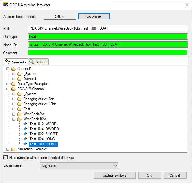
If you open the symbol browser from the signal tables instead of via the hyperlink in the General tab, then you will already be shown the tags with the corresponding data types.