The configuration dialog offers the possibility to configure two DCF77 signals. In this way, a redundant time management can be realized.
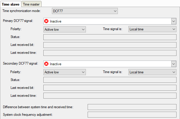
Primary DCF77 signal
In this field, select the digital input signal which is used for transmitting the decoded DCF77 signal. Click on the little arrow button in the field. A signal tree showing all available modules and signals opens. Select the appropriate signal by mouse click.
Polarity
In this field, select the correct polarity of the pulse. Depending on the device type you are using, the control pulse may be logical "1" (TRUE) or logical "0" (FALSE). Please refer to the manual of the DCF77 receiver and set the correct polarity.
Time signal is
Open this selection field in order to set the time mode of the DCF77 signal. Available for selection are:
-
Local time
-
UTC time (Universal Time Coordinated)
-
UTC time with DST compensation
Comment: DST stands for daylight saving time. In this mode, ibaPDA will convert the time from UTC to local time just like in the normal UTC time mode. If the daylight saving time bit is set in the telegram, ibaPDA will subtract 1 hour to compensate the daylight saving time. In all other modes, the daylight saving time bit is ignored.
Status
Clear text messages regarding the DCF77 connection are displayed here.
|
Status |
Meaning |
|---|---|
|
Inactive |
DCF77 synchronization is disabled. |
|
Invalid |
An invalid sequence of bits was received (parity error). |
|
Valid |
ibaPDA is synchronized with DCF77, a sequence was received. |
|
Sequence received |
A complete sequence (bits 0 to 59) was received. |
|
Signal received |
A minute pulse was received. |
|
Signal lost |
No minute pulse was received. |
Last received bit
This line displays the bit no. and the value of the last received bit. Bit no. 0 ... 59, value: 0 (FALSE) or 1 (TRUE). With the DCF77 decoding scheme, it is possible to get the meaning of the bit. For service purposes only.
Last received time
This line displays the last received time as clear text in the format dd/mm/yy hh:mm:ss.ms. This shows the time of the last synchronization of the system.
Difference between system time and received time
The received time is cyclically compared with the system time whereas deviation is determined. Depending on whether the difference is rather positive or rather negative, a corresponding frequency adjustment of the internal system clock is calculated.
System clock frequency adjustment
The value of the frequency adjustment has been determined from the difference between the system time and the received time. Thus, a system clock which is too fast or too slow is corrected.