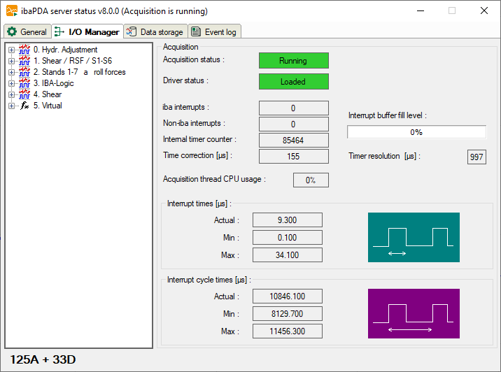
Acquisition
This dialog offers relevant information about data acquisition.
Beside the signal tree, which contains all defined modules and signals, you can see whether or not the acquisition (=measurement) is running. Below the signal tree, you will find the number of currently used signals (analog and binary).
The display for the driver status (ibaPDA driver) must show the "Loaded" status on green background for proper operation. In case of a failure, the field turns red and an error message appears below the start button. If, for example, another process is already running with ibaPDA-drivers, the message would indicate that an instance of the program is already running.
In addition, you will find a number of displays that reflect the interrupt behavior. The interrupts are good indicators of the proper function of the system.
iba interrupts
This is an interrupt counter for interrupts, which are generated by iba PC cards. In proper operation, it counts up with a rate of 1000 / sec corresponding to an interrupt cycle of 1 ms.
Non-iba interrupts
This counter will only change if other cards in the computer generate interrupts. This could occur in case of “shared interrupts”. If the iba card generating the interrupt is assigned an exclusive interrupt, the counter must not change.
Internal timer counter
The internal timer counter is active when no interrupt source (PC card) is available. In this case the Windows timer is used.
The counter usually also count upwards with 1000 / sec.
Time correction
The value for time correction will only be displayed during acquisition and the internal timer counter serves as interrupt source. Generally, the internal timer counter has not exactly the same resolution like the basic sample time. Hence, each counter step has a deviation of a few microseconds. These microseconds are added in the time correction counter. As soon as the sum matches the timer resolution, a double counter pulse will be triggered. This method enables the internal timer to match the basic sample time in average.
Acquisition thread CPU usage
This is the CPU time the server needs to read data from the driver and process them, e.g. evaluation of virtual signals, writing to the data file, buffering for transmission to clients etc.
Interrupt buffer (fill level)
This display shows how much data is in the interrupt buffer of the driver.The ibaPDA server periodically reads from this buffer. If the interrupt service routine (ISR) of the driver takes too long, the ibaPDA server has not enough time to read all data out of the buffer and the buffer overflows. This would cause a stop of the acquisition. In that case, either a reduction of the number of signals or an increase of the basic sample time is required in order to ensure proper operation. This would reduce the read-out time for the ISR.
In the I/O-Manager – General tab – Interrupt Info node you may increase the size of the interrupt buffer up to 1024 MB, in order to prevent fast buffer overflow. Default size of the buffer is 50 MB.
Timer resolution
This time value given in ms should approximately correspond to the measurement time base. The timer is used for the internal generation of interrupts.
Interrupt times
These values are only displayed when the acquisition is running.
The system measures the actual processing time of the ISR (=interrupt time) and stores the shortest (Min) and longest (Max) time. The ISR reads the requested data from the different PC cards. The ratio of interrupt time to interrupt cycle time shows the percentage of CPU time required to read the data from the cards.
The actual interrupt time should never exceed double the interrupt cycle time. If so, interrupts will get lost and the measurement is not accurate.
Interrupt cycle times
These values are only displayed when the acquisition is running. The system measures the actual cycle time of the interrupt and stores the shortest (Min) and longest (Max) time.