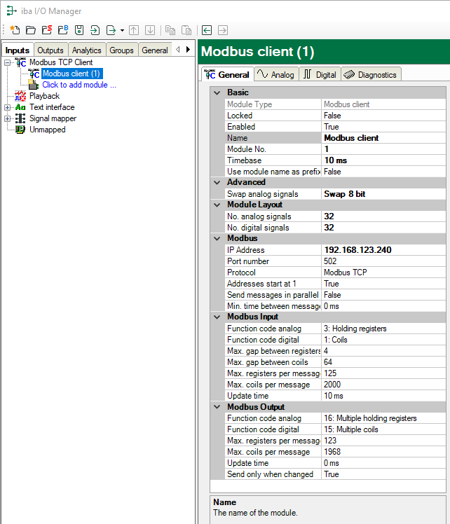
To configure a module, select it in the tree structure.
All modules have the following setting options.
Basic settings
Module Type (information only)
Indicates the type of the current module.
Locked
You can lock a module to avoid unintentional or unauthorized changing of the module settings.
Enabled
Enable the module to record signals.
Name
You can enter a name for the module here.
Comment
You can enter a comment or description of the module here. This will be displayed as a tooltip in the signal tree.
Module No.
This internal reference number of the module determines the order of the modules in the signal tree of ibaPDA client and ibaAnalyzer.
Timebase
All signals of the module are sampled on this timebase.
Use module name as prefix
This option puts the module name in front of the signal names.
Advanced
Swap analog signals
Option to change the order of the byte evaluation.
Tip |
|
|---|---|
|
For a Modicon M580 system select the setting "Swap 8 bit"! |
|
Module Layout
No. analog signals/No. digital signals
Define the number of configurable analog and digital signals in the signal tables. The default value is 32 for each. The maximum value is 1000. The signal tables are adjusted accordingly.
Modbus
IP address
IP address of the Modbus server.
Port number
By default, the port number is set to the standard port 502.
Protocol
"Modbus TCP" is the default setting. Optionally, you can select "Modbus serial". Thus, the serial RTU-Modbus protocol is selected, that is transmitted via TCP/IP. Use this protocol, in case the device is connected to an Ethernet/serial gateway, e. g. the IF2E001 from IME. See Modbus Protocol
Addresses start at 1
For Modbus, the internal areas (Registers, Coils) are numbered starting at 1; the reference addresses are numbered beginning with 0.
True: The addresses on the Analog and Digital tabs start at 1.
False: The addresses on the Analog and Digital tabs start at 0.
Tip |
|
|---|---|
|
For a Modicon M580 system select the setting "False"! |
|
Send messages in parallel
True: All messages that are needed for reading the signals of this module are sent in parallel; then it waits for responses.
False: After each request message, the system waits for the response message, only then the next request message will be sent.
Min. time between messages
Specify the minimum time interval at which the telegrams are sent to the Modbus server. 0 means that all telegrams are sent directly one after the other.
Modbus Input
Function code analog
Choose the analog data type “Holding registers” or “Input registers”.
Function code digital
Choose the digital data type "Coils", "Discrete inputs" or "Holding registers". With "Holding registers", you can acquire single bits from holding registers.
Maximum gap between registers
Registers that are not consecutive, are sent in a request, if the gaps between the registers are not larger than the specified value. The default setting is 4.
Maximum gap between coils
Coils or Input bits that are not consecutive are sent in a request, if the gaps between the bit addresses are not larger than the specified value.The default setting is 64.
Max. registers/coils per message
Here the maximum number of registers or coils per message can be determined. By default the values, usually entered according to the standard, are specified. Some devices allow other registers or coils per message, which can be set here.
Update time
The update time determines how fast the data are being requested by the Modbus server. The standard equals the parameter "Timebase".
Modbus Output
see section "Modbus Input".
Send only when changed
False: The output message is sent in the update cycle specified above
True: The output message is only sent after a value in the message has been changed, but no later than 1 min.
